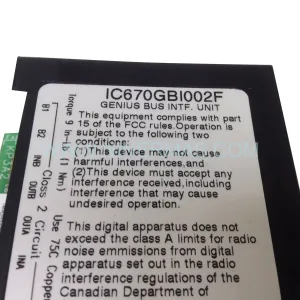
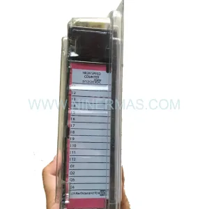
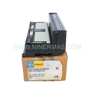
Original Industrial Spare Part
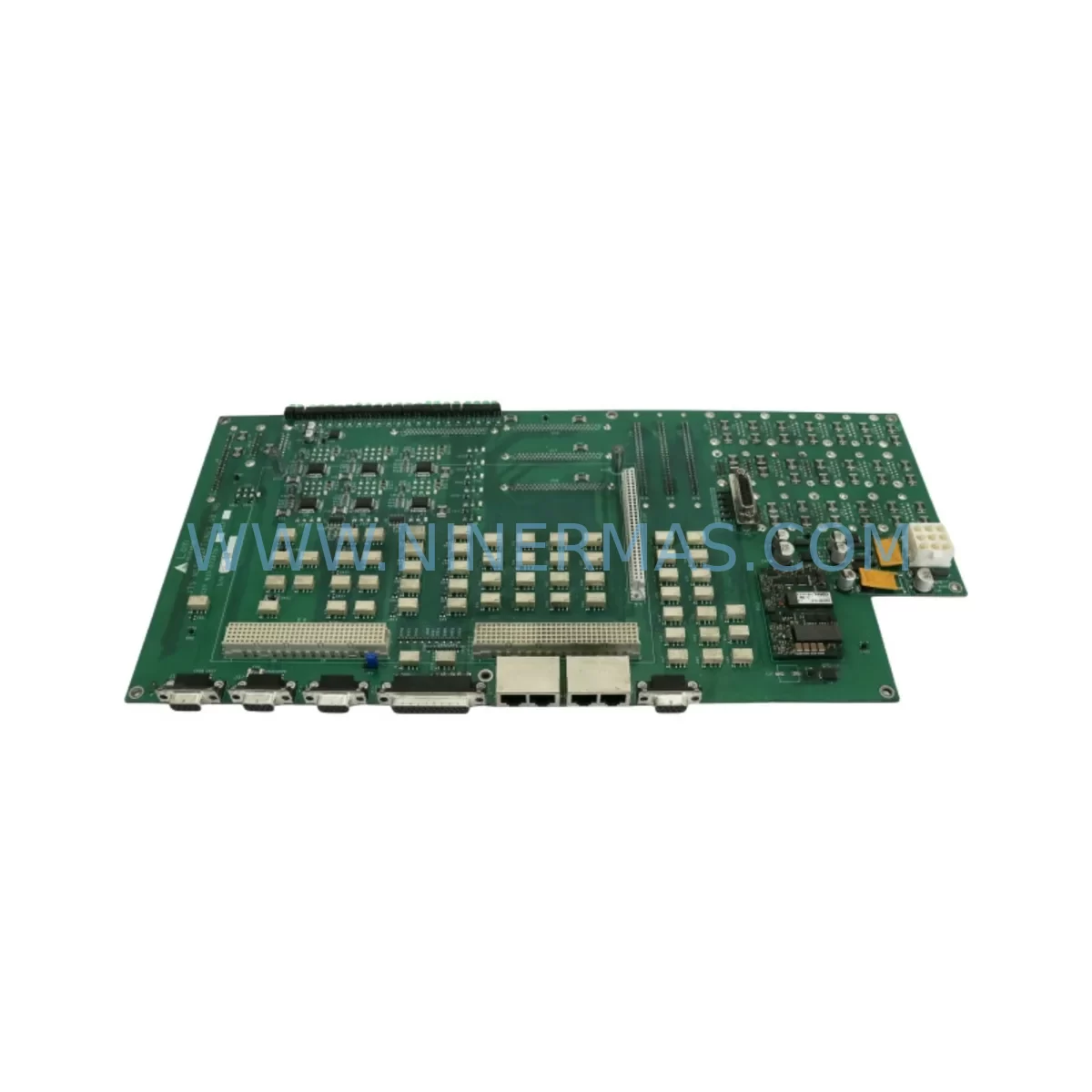
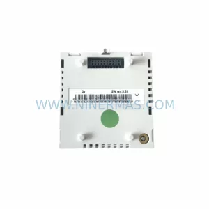
LAM RESEARCH 710-073479-215 Retrofit PCB for Legacy Systems
Verify the part, confirm the platform family, and move straight into quotation with the right commercial details.
RFQ Ready
- SKU710-073479-215 810-073479-215 5V - 15V X9-2L2L1D-000001 5V - 12V X7-2D2J2J-000001
- CategoryPLC & Industrial Automation Modules
- BrandLam Research
- SupportAvailability, lead time, condition, and shipping coordination
How Buyers Usually Use This Page
- Confirm the exact part number and platform family before sending the quote request.
- Use direct email when quantity, condition, and destination are already defined internally.
- Switch to the broader brand or category archive when you need alternates nearby.
Series Navigation
Move through the most common platform families behind this part.
Product RFQ
Send this part directly for quotation.
Include quantity, required condition, destination country, and target delivery timing. Current reference: LAM RESEARCH 710-073479-215 Retrofit PCB for Legacy Systems with SKU 710-073479-215 810-073479-215 5V - 15V X9-2L2L1D-000001 5V - 12V X7-2D2J2J-000001.
LAM RESEARCH 710-073479-215 Retrofit PCB for Legacy Systems: Seamless Compatibility and Smooth Upgrade
The LAM RESEARCH 710-073479-215 is a ruggedized printed circuit board assembly engineered for demanding semiconductor processing environments. As legacy etch and deposition systems approach end-of-life, this PCB serves as a critical retrofit-compatible replacement for facilities seeking to extend the operational lifespan of their existing LAM Research platforms without committing to a full system overhaul. Whether you are managing a Kiyo, Versys, or Rainbow-series etch chamber, the 710-073479-215 provides a validated drop-in upgrade path that preserves your existing control architecture while restoring full system functionality.
This board is cross-referenced against the alternate part number 810-073479-215, and is compatible with the X9-2L2L1D-000001 and X7-2D2J2J-000001 control configurations operating on 5V–15V and 5V–12V supply rails respectively. Before installation, engineers should verify the power rail tolerance at the backplane connector, confirm terminal block pinout against the original wiring diagram, and validate module address assignments within the system’s PLC configuration to avoid address conflicts during first-boot initialization.
Upgrade Compatibility Table
| Parameter | Original / Legacy Spec | 710-073479-215 Retrofit Spec | Notes |
|---|---|---|---|
| Supply Voltage | 5V / 12V / 15V | 5V–15V multi-rail compatible | Verify backplane rail before installation |
| Form Factor | Standard LAM PCB slot | Direct slot-in replacement | Confirm rack depth and card guide clearance |
| Communication Interface | Proprietary LAM serial bus | Compatible with existing bus topology | No protocol migration required |
| Module Address | DIP switch / firmware-set | Configurable via onboard DIP | Match original address before power-on |
| I/O Compatibility | Legacy I/O mapping | Fully backward-compatible I/O | Validate signal mapping in PLC program |
| HMI Screen Compatibility | Existing HMI panel | No HMI reconfiguration required | Confirm alarm tag mapping post-swap |
| Installation Space | Standard 19″ control cabinet | Same footprint as original | No mechanical modification needed |
| Warranty | N/A (end-of-life part) | 12-Month Warranty | Covered by NINERMAS quality guarantee |
Retrofit Planning for Existing Automation Systems
Successful integration of the 710-073479-215 into a legacy LAM Research system requires a structured pre-installation audit. Begin by documenting the existing backplane assembly — typically identified under part references such as the 853-073479 series — to confirm slot position, card guide alignment, and bus connector condition. A damaged backplane connector is one of the most common causes of intermittent faults after a PCB swap and should be inspected and cleaned before the new board is seated.
Power supply integrity is equally critical. The 810-073479-215 power module, which feeds the logic and I/O sections of the control board, must be load-tested prior to the retrofit. An aging power supply delivering marginal voltage under load will cause the replacement PCB to exhibit erratic behavior that can be misdiagnosed as a board fault. Confirm that all supply rails are within ±5% of nominal under full I/O load before proceeding.
For systems utilizing the 710-073479-214 revision board in adjacent slots, verify that the firmware revision on the 710-073479-215 is compatible with the inter-board communication protocol used across the rack. In multi-board configurations, a firmware mismatch between the 710-073479-214 and the replacement 710-073479-215 can cause handshake failures on the internal serial bus, resulting in fault codes that appear unrelated to the board swap.
I/O expansion modules — such as the 660-073479 series digital I/O cards — should be re-enumerated after the PCB replacement to ensure the system controller correctly identifies all connected modules. The 810-800256 system controller may require a soft reset to refresh its module map following the swap. This is a standard procedure and does not require reprogramming of the main control logic.
Communication link integrity between the control board and the HMI interface panel (referenced under the 660-900256 HMI interface assembly) should be validated using the system’s built-in diagnostic mode before returning the chamber to production. Pay particular attention to alarm tag mapping: legacy HMI screens may reference tag addresses that need to be confirmed against the new board’s I/O register layout.
Signal conditioning boards such as the 713-073479 series, which handle analog input scaling for process sensors, should also be inspected during the retrofit window. These boards are frequently overlooked but are a common source of process drift after a control board replacement. Similarly, the 810-495659 servo drive module, if present in the same control cabinet, should be checked for firmware compatibility with the updated control board.
Finally, confirm that the 853-800256 rack assembly provides adequate grounding continuity at all card slots. Poor rack grounding is a known contributor to EMI-induced faults in high-frequency etch environments and can cause the replacement PCB to exhibit noise-related errors that are difficult to trace without proper grounding verification.
Downtime Control During System Migration
Minimizing unplanned downtime during a PCB retrofit requires preparation that begins well before the maintenance window opens. The most effective approach is to pre-configure the 710-073479-215 offline: set the DIP switch module address to match the original board, verify the supply voltage compatibility, and perform a bench-level power-on test using a controlled 5V/12V bench supply before the board enters the production environment.
Preserve the original PLC program backup before any hardware change. Even a direct drop-in replacement can trigger unexpected behavior if the program logic contains hardware-specific calibration offsets or timer values that were tuned to the characteristics of the original board. Having a verified program backup allows rapid rollback if the system does not respond as expected after the swap.
During the swap itself, follow a structured sequence: power down the chamber, discharge any stored energy in the power supply capacitor bank, remove the failed board, seat the replacement 710-073479-215, verify connector engagement, restore power, and monitor the system’s startup diagnostic sequence before releasing the chamber to process. This sequence typically allows a controlled swap to be completed within a single maintenance shift, keeping unplanned downtime to a minimum.
Post-installation, run the chamber through a dry process cycle before returning it to production wafer processing. This confirms that all I/O signals, communication links, and process control loops are functioning correctly under real operating conditions without risking product yield.
Retrofit Support FAQ
Q1: Is the 710-073479-215 a direct replacement for the 810-073479-215?
A: The 710-073479-215 and 810-073479-215 are cross-referenced part numbers for the same PCB assembly used in different LAM Research system configurations. Confirm the part number against your system’s bill of materials before ordering. NINERMAS can assist with cross-reference verification prior to shipment.
Q2: What pre-shipment testing is performed on this board?
A: Every 710-073479-215 unit shipped by NINERMAS undergoes functional power-on testing, I/O continuity verification, and visual inspection for component integrity. A test report is available upon request. All units are covered by a 12-month warranty from the date of shipment.
Q3: Do I need to reconfigure my PLC program after installing this board?
A: In most cases, no. The 710-073479-215 is designed as a drop-in replacement that maintains backward compatibility with existing PLC program logic. However, you should verify module address settings via the onboard DIP switches and confirm I/O tag mapping in your HMI before returning the system to production.
Q4: What is the lead time and stock availability?
A: NINERMAS maintains ready stock of the 710-073479-215 to support urgent maintenance requirements. Standard lead time for in-stock units is 3–7 business days for international shipment. Contact sale@ninermas.com or call +0086 187 5021 5667 for real-time stock confirmation and expedited shipping options.
| Product Series | Legacy |
|---|
Catalog Continuation
More Lam Research modules in the catalog.
Use the brand lane to compare nearby part numbers, platform-adjacent modules, and other inquiry-ready listings before sending your final RFQ.
SKU: 839-182861-001 0100-00698 0090-02346 0010-09348
LAM 839-182861-001 Retrofit Valve Module for Legacy Systems
SKU: DGF 710-031325-002 810-031325-002 LAM 716-443129-001 10320294 810-UNV
Lam 710-031325-002 Retrofit-Compatible DGF for Legacy Systems
SKU: 810-802799-010 810-031325-003 0021-28413 0021-32929
Lam Research 810-802799-010 Retrofit Module for Legacy Systems
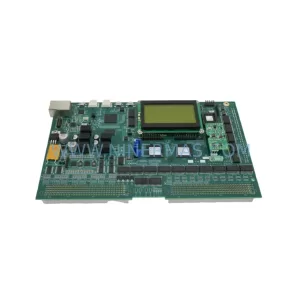
SKU: UI/FIB JTS SIH4 W/ BD 24 810-111093-100 C1848 , TVB41D-1/TMP 1D81-000140 853-250063-007
Lam Research 810-111093-100 Retrofit Gas Module for Legacy Systems
Catalog Continuation
Alternative parts within PLC & Industrial Automation Modules.
Stay inside the same system family when you need substitutes, adjacent modules, or a broader shortlist for procurement review.
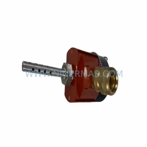
SKU: TRY/PRG/4-20MA/10-30DC
MOORE TRY/PRG/4-20MA/10-30DC Service-Ready Spare Part
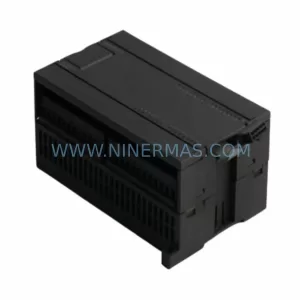
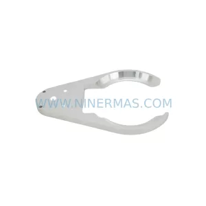
SKU: 5085-404901-11 12INCH 2910-202413-12 404200XRMPD2H14 7-249717
TEL 5085-404901-11 Service-Ready Spare Part for Industrial Maintenance
SKU: DIP011 05-058-011
SIGMATEK DIP011 05-058-011 Service-Ready Spare Part