Original Industrial Spare Part
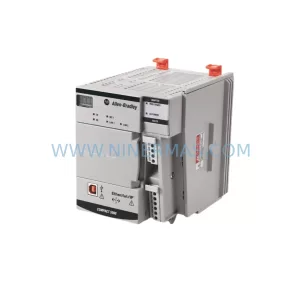
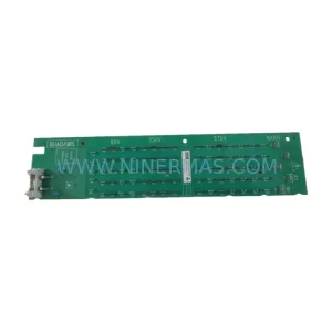
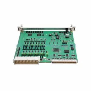
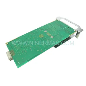
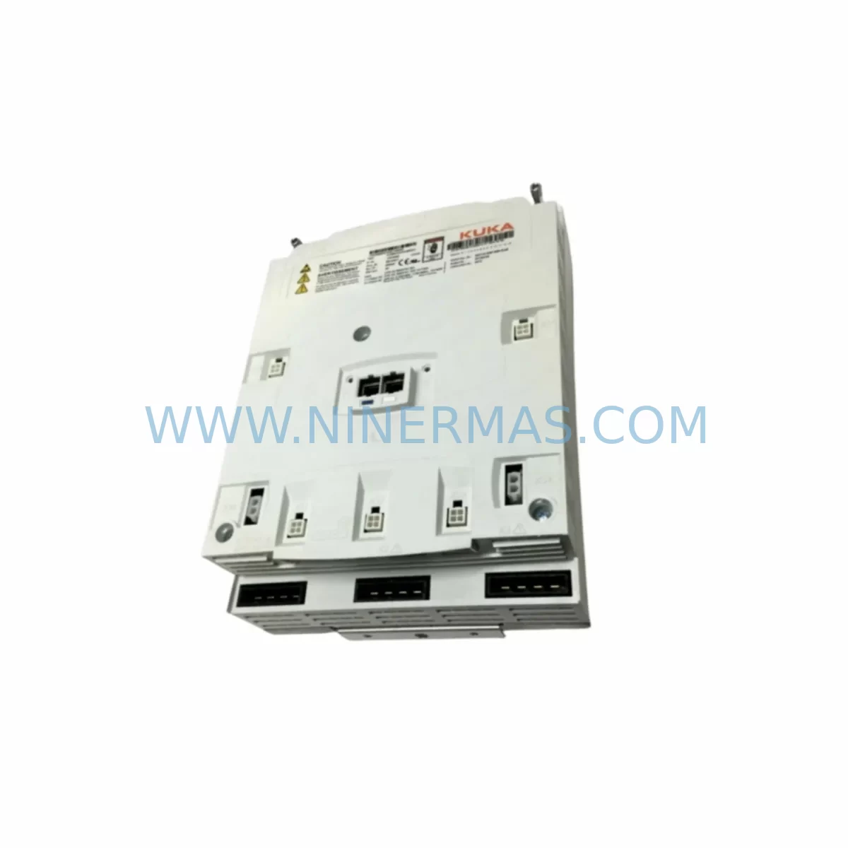
KUKA KPP-600-20 Retrofit Power Supply for Legacy Systems
Verify the part, confirm the platform family, and move straight into quotation with the right commercial details.
RFQ Ready
- SKUKPP 600-20 2X40 :00-160-152 KPP 600-20 3X20 UL :00-245-213 KPP 600-20 UL :00-198-259
- CategoryPLC & Industrial Automation Modules
- BrandKUKA
- SupportAvailability, lead time, condition, and shipping coordination
How Buyers Usually Use This Page
- Confirm the exact part number and platform family before sending the quote request.
- Use direct email when quantity, condition, and destination are already defined internally.
- Switch to the broader brand or category archive when you need alternates nearby.
Series Navigation
Move through the most common platform families behind this part.
Product RFQ
Send this part directly for quotation.
Include quantity, required condition, destination country, and target delivery timing. Current reference: KUKA KPP-600-20 Retrofit Power Supply for Legacy Systems with SKU KPP 600-20 2X40 :00-160-152 KPP 600-20 3X20 UL :00-245-213 KPP 600-20 UL :00-198-259.
KUKA KPP-600-20 Retrofit Power Supply for Legacy Systems
The KUKA KPP-600-20 series power supply module — covering part numbers KPP-600-20-2X40 (00-160-152), KPP-600-20-3X20-UL (00-245-213), and KPP-600-20-UL (00-198-259) — is a critical component in KUKA KRC-generation robot controller cabinets. As these controllers age and original spare parts become increasingly scarce, the KPP-600-20 remains one of the most sought-after retrofit-compatible power supply units for legacy system modernization. Whether you are replacing a failed unit in an existing KRC2 or KRC3 cabinet, upgrading a production line to extend its operational life, or sourcing a long-term spare to protect against future downtime, the KPP-600-20 series provides a direct, drop-in compatible solution for legacy KUKA automation platforms.
Upgrade Compatibility Table
| Attribute | KPP-600-20-2X40 (00-160-152) | KPP-600-20-3X20-UL (00-245-213) | KPP-600-20-UL (00-198-259) |
|---|---|---|---|
| Output Power | 600 W, 2×40 A | 600 W, 3×20 A | 600 W, UL-rated |
| Compatible Controller | KRC2, KRC3 | KRC2, KRC3 | KRC2, KRC3 (UL market) |
| Backplane Interface | KRC standard backplane | KRC standard backplane | KRC standard backplane |
| Installation Space | Standard KRC cabinet slot | Standard KRC cabinet slot | Standard KRC cabinet slot |
| Communication Compatibility | DeviceNet, Profibus | DeviceNet, Profibus | DeviceNet, Profibus |
| Replacement Recommendation | Direct swap; verify output rail wiring | Direct swap; verify 3-rail load balance | Direct swap; confirm UL certification requirement |
| Commissioning Focus | Output voltage calibration, fan check | Rail current distribution, thermal check | UL compliance verification, output check |
| Warranty | 12 Months | 12 Months | 12 Months |
Retrofit Planning for Existing Automation Systems
Replacing the KPP-600-20 in an operational KUKA robot cell requires careful pre-migration planning to avoid extended downtime and protect existing program logic. Before removing the failed unit, engineers should document the current wiring configuration at the X11 connector block, which carries the primary power input to the KRC cabinet. Verifying the incoming three-phase supply voltage and confirming that the cabinet’s main circuit breaker rating matches the replacement unit’s input specification is an essential first step.
The KPP-600-20 interfaces directly with the KRC backplane, distributing regulated DC power to downstream modules including the KSD1-16 servo drive boards, the CCU (Cabinet Control Unit) board, and the SIB (Safety Interface Board). When the power supply is replaced, each of these modules must be inspected for proper seating on the backplane before power-up. The RDC (Resolver-to-Digital Converter) board, which handles motor feedback signals, is particularly sensitive to power transients during startup and should be checked for firmware integrity after any power supply swap.
For systems running KUKA System Software (KSS) on the KRC2 or KRC3 platform, the KCP4 teach pendant connection should be verified after the replacement. The teach pendant communicates with the controller via the internal KPC (KUKA PC) over a dedicated data link; any interruption in the power supply chain can cause the pendant to lose its session state, requiring a cold restart sequence. Operators should have the KSS version number and robot configuration backup available before beginning the swap.
In cells where the KRC cabinet also hosts a Profibus DP or DeviceNet communication module for PLC integration, the fieldbus node address and baud rate settings stored in the communication module’s non-volatile memory should be recorded prior to the replacement. After the new KPP-600-20 is installed and the system powers up, the fieldbus master (typically a Siemens S7-300 or S7-400 PLC, or an Allen-Bradley ControlLogix controller) should be monitored for node re-registration to confirm that the communication link has been restored without address conflicts.
Where the robot cell includes an ESC-CI (Electronic Safety Circuit) module for safety-rated stop functions, the safety circuit must be re-validated after any power supply replacement. This includes testing the E-stop chain, the safety gate interlock, and the operator enable switch to confirm that the ESC-CI module is receiving correct power and that all safety outputs are functioning within specification. This step is mandatory in safety-critical applications and should be documented in the site’s maintenance log.
For facilities managing multiple KUKA robots on a shared production line, it is advisable to maintain at least one KPP-600-20 unit in reserved inventory. The KPS-600-20 and KSP-600-20 servo power supply variants used in adjacent KRC cabinets share similar form factors and should be stocked alongside the KPP-600-20 to cover a broader range of failure scenarios without requiring emergency procurement. Coordinating with your procurement team to establish a long-term supply agreement for KPP-series components can significantly reduce mean time to repair (MTTR) targets to the 4–6 hour range.
Downtime Control During System Migration
Minimizing production downtime during a KPP-600-20 replacement begins with pre-staging the replacement unit and all required tools before the maintenance window opens. The KRC cabinet should be de-energized following the site’s lockout/tagout (LOTO) procedure, with the main isolator locked and the DC bus capacitors fully discharged before any internal work begins. Discharge time for the KRC2 and KRC3 bus capacitors is typically five minutes after power removal; this interval must be observed to protect both personnel and sensitive electronics.
Once the failed KPP-600-20 is removed, the replacement unit should be inspected for shipping damage and its output voltage labels verified against the cabinet’s wiring diagram before installation. After mechanical installation and wiring reconnection, a controlled power-up sequence — starting with the cabinet’s 24 VDC auxiliary supply before enabling the main AC input — allows the CCU board and SIB module to initialize and report any fault codes before the servo drives are energized. This staged power-up approach protects the KSD1-16 servo boards from potential inrush events and gives the control system time to complete its self-diagnostic routines.
Original robot program logic stored on the KPC hard drive or CompactFlash card is not affected by a power supply replacement, provided the storage media remains undisturbed during the swap. However, it is best practice to verify that the robot’s zero-point calibration data and tool/base coordinate frames are intact after the first powered test cycle. Any deviation in mastering data should be corrected before returning the robot to automatic production mode.
Retrofit Support FAQ
Q1: Is the KPP-600-20-2X40 (00-160-152) a direct replacement for the KPP-600-20-UL (00-198-259)?
The two variants share the same 600 W power class and KRC backplane interface, but the UL-suffix variant carries UL certification for North American market compliance. In UL-regulated facilities, the KPP-600-20-UL (00-198-259) must be used. In non-UL markets, the KPP-600-20-2X40 is functionally equivalent for most KRC2 and KRC3 applications. Always confirm the output rail configuration (2×40 A vs. UL-rated single output) against your cabinet’s wiring diagram before substituting variants.
Q2: What pre-shipment testing is performed on KPP-600-20 units?
Each KPP-600-20 unit supplied by NINERMAS undergoes a full functional power-on test prior to shipment. Output voltage levels on all rails are measured and recorded, fan operation is verified, and the unit is inspected for physical integrity. A 12-month warranty is provided from the date of shipment, covering defects in materials and workmanship under normal operating conditions.
Q3: How do I confirm wiring compatibility before installing the replacement unit?
Refer to the KRC2 or KRC3 cabinet wiring diagram specific to your robot model and year of manufacture. Pay particular attention to the X11 connector pinout for the primary AC input, the DC output rail assignments to the backplane, and the fan power connections. If the original wiring diagram is unavailable, NINERMAS technical support can assist in identifying the correct configuration based on your robot’s serial number and KSS version.
Q4: What is the lead time and inventory availability for KPP-600-20 series units?
NINERMAS maintains reserved inventory of KPP-600-20-2X40, KPP-600-20-3X20-UL, and KPP-600-20-UL units to support urgent replacement requirements. Standard lead time for in-stock units is 3–5 business days for international shipment. For facilities with recurring demand, long-term supply agreements with reserved stock allocation are available to eliminate procurement lead time risk and ensure continuity of spare parts supply across multi-robot installations.
| Product Series | Legacy |
|---|---|
| Country of Origin | DE |
Catalog Continuation
More KUKA modules in the catalog.
Use the brand lane to compare nearby part numbers, platform-adjacent modules, and other inquiry-ready listings before sending your final RFQ.
SKU: 00-207-218 C4 GA12
KUKA 00-207-218 GA12 Retrofit Drive for Legacy Systems
SKU: 00-106-446kr150.kr180 ZH150/180
KUKA 00-106-446 Retrofit-Compatible Gearbox for Legacy Systems
Catalog Continuation
Alternative parts within PLC & Industrial Automation Modules.
Stay inside the same system family when you need substitutes, adjacent modules, or a broader shortlist for procurement review.