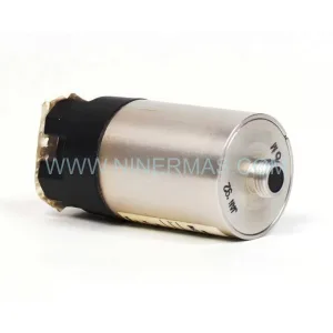
Original Industrial Spare Part
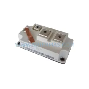
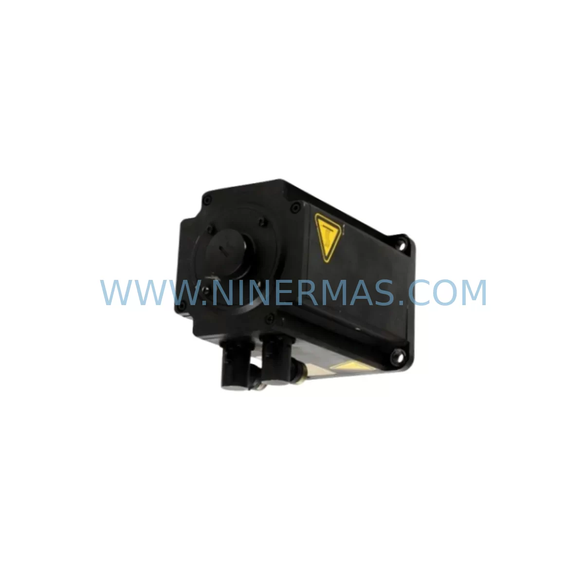
KUKA 1FK7063-5AF71-1SY3-ZS77 Retrofit Servo for Legacy Systems
Verify the part, confirm the platform family, and move straight into quotation with the right commercial details.
RFQ Ready
- SKU00-219-254 GA12-A-FO 00-198-260.KPP600-20-1X40 C4 00-179-159 1FK7063-5AF71-1SY3-ZS77
- CategoryPLC & Industrial Automation Modules
- BrandKUKA
- SupportAvailability, lead time, condition, and shipping coordination
How Buyers Usually Use This Page
- Confirm the exact part number and platform family before sending the quote request.
- Use direct email when quantity, condition, and destination are already defined internally.
- Switch to the broader brand or category archive when you need alternates nearby.
Series Navigation
Move through the most common platform families behind this part.
Product RFQ
Send this part directly for quotation.
Include quantity, required condition, destination country, and target delivery timing. Current reference: KUKA 1FK7063-5AF71-1SY3-ZS77 Retrofit Servo for Legacy Systems with SKU 00-219-254 GA12-A-FO 00-198-260.KPP600-20-1X40 C4 00-179-159 1FK7063-5AF71-1SY3-ZS77.
KUKA 1FK7063-5AF71-1SY3-ZS77 Retrofit Servo for Legacy Systems
The KUKA 1FK7063-5AF71-1SY3-ZS77 is a SIMOTICS S-1FK7 series permanent-magnet synchronous servo motor widely deployed in KUKA industrial robot arms, automated welding cells, and precision motion control platforms. As original equipment reaches end-of-life and OEM support windows close, facilities engineering teams face increasing pressure to source verified replacement units that preserve existing wiring harnesses, resolver feedback circuits, and KRC controller configurations without triggering a full system redesign. This product is stocked, pre-shipment tested, and backed by a 12-month warranty to support planned maintenance cycles and emergency breakdown recovery alike.
The 1FK7063-5AF71-1SY3-ZS77 designation encodes critical application parameters: the 1FK7063 frame size delivers a rated torque output suited to axis-2 and axis-3 positions in mid-range KUKA robot models; the 5AF71 winding variant defines the voltage and speed class; 1SY3 specifies the shaft and flange configuration; and ZS77 identifies the resolver feedback option with specific connector orientation. Procurement teams and maintenance engineers must verify each code segment against the robot’s axis data sheet before ordering to ensure dimensional and electrical compatibility.
Upgrade Compatibility Table
| Parameter | 1FK7063-5AF71-1SY3-ZS77 (This Unit) | Retrofit Notes |
|---|---|---|
| Frame / Flange | 63 mm flange, 1SY3 shaft | Verify mounting bolt pattern against robot arm casting; no adapter plate required for direct replacement |
| Feedback Type | Resolver (ZS77 orientation) | Compatible with KUKA RDC (Resolver Digital Converter) board; no encoder swap required |
| Winding / Speed Class | 5AF71 (400 V class) | Confirm KPP600 DC bus voltage and KSD servo drive current rating before installation |
| Connector Interface | X11 power + X20 resolver | Retain original KUKA motor cable set; inspect pin seating and O-ring condition |
| Installation Space | Standard KUKA axis housing | Measure clearance at cable exit; ZS77 connector orientation must match original routing |
| Communication Link | Resolver signal via RDC to KRC4 | No fieldbus reconfiguration required; resolver offset may need re-calibration in WorkVisual |
| Replacement Scope | Drop-in for same SKU; cross-reference 1FK7063-5AF71-1SY3 variants | Confirm ZS suffix matches existing cable harness connector exit direction |
| Pre-Shipment Test | Insulation resistance, no-load run, resolver signal check | Test certificate available on request |
| Warranty | 12 Months | Covers winding insulation, bearing, resolver, and shaft seal under normal operating conditions |
Retrofit Planning for Existing Automation Systems
Successful integration of the 1FK7063-5AF71-1SY3-ZS77 into an existing KUKA robot cell requires a structured pre-retrofit audit covering power capacity, terminal wiring, backplane interfaces, module addressing, program compatibility, HMI screens, communication links, installation space, and on-site commissioning procedures.
Begin with the power supply chain. The KPP600-20-2×40 cabinet power supply module feeds the DC bus shared by all axis drives in the KRC4 cabinet. Before swapping the servo motor, confirm that the KPP600 bus voltage is within specification and that the associated KSD1-16 or KSP600-3×20 servo drive module assigned to the affected axis is not showing fault codes related to overcurrent or resolver signal loss. A degraded drive module can mask the true source of motor failure and lead to repeat breakdowns after the motor replacement.
Next, inspect the motor cable harness. The X11 power connector and X20 resolver connector must be checked for pin corrosion, bent contacts, and damaged O-ring seals. Reusing a compromised cable with a new motor introduces resolver signal noise that the RDC board interprets as position error, triggering KRC4 safety stops. If the cable shows wear, replace it alongside the motor to avoid a second unplanned outage.
For axis mastering, the KUKA smartPAD (KCP4) is used to run the Electronic Mastering Device (EMD) procedure after motor installation. The mastering offset stored in the robot controller must be updated to reflect the new motor’s resolver zero position. Skipping this step results in axis position drift and potential collision with tooling or fixtures. Document the pre-replacement mastering values as a rollback reference.
Where the robot cell includes a KUKA CCU (Cabinet Control Unit) board managing safety I/O and axis enable signals, verify that the safety circuit remains intact after motor removal. The CCU monitors motor temperature via the KTY sensor embedded in the 1FK7063 winding. Confirm the KTY wiring continuity in the X11 connector before closing the cabinet.
For cells running coordinated motion with external axes — such as a servo-driven positioner using a 1FK7042-5AF71-1SY3 motor on a smaller axis or a 1FK7083-5AF71-1SY3 on a heavier load axis — verify that the axis synchronization parameters in the KRC4 motion program remain valid after the replacement. A change in resolver calibration on one axis can affect coordinated path accuracy across the entire cell.
HMI screens built in KUKA.HMI or third-party SCADA systems that display axis torque, temperature, or position data should be reviewed after commissioning to confirm that signal scaling and alarm thresholds remain correct. No program logic changes are required for a same-SKU motor replacement, but the mastering update will shift position feedback values that some HMI trend displays capture.
Finally, confirm installation space at the motor mounting location. The ZS77 connector orientation on the 1FK7063-5AF71-1SY3-ZS77 determines cable exit direction. In tight axis housings, an incorrect connector orientation forces the cable into a bend radius below the minimum specified, accelerating insulation fatigue. Cross-reference the connector exit angle against the robot’s axis assembly drawing before accepting delivery.
Downtime Control During System Migration
Minimizing unplanned downtime during a servo motor replacement on a production robot requires preparation that begins before the maintenance window opens. The original program logic stored in the KRC4 controller does not need to be modified for a same-SKU motor swap, but a full controller backup using WorkVisual should be completed and archived before any mechanical work begins. This backup captures axis configuration, safety parameters, motion programs, and I/O assignments, providing a complete restore point if the commissioning process encounters unexpected faults.
Mechanical removal of the 1FK7063-5AF71-1SY3-ZS77 from the robot arm should follow the KUKA axis replacement procedure, which specifies torque values for flange bolts and the correct sequence for releasing the motor brake before disconnecting power. Failure to release the brake before disconnecting the KSD drive can result in uncontrolled axis movement when the brake circuit loses power.
After installing the replacement motor and reconnecting the X11 and X20 connectors, perform a cold start of the KRC4 controller and monitor the boot sequence for resolver fault codes. If the RDC board reports a resolver signal error, recheck connector seating before assuming a faulty motor. Once the controller reaches operational state, run the EMD mastering procedure on the affected axis, verify mastering values against the documented pre-replacement baseline, and execute a slow-speed test cycle through the full axis range before resuming production speed.
For facilities managing multiple robot cells with the same axis configuration, maintaining a reserved stock of 1FK7063-5AF71-1SY3-ZS77 units reduces mean time to repair (MTTR) from days to hours. Pre-tested spare units with documented resolver calibration data can be installed and commissioned within a single shift, keeping production loss within acceptable limits for most manufacturing SLA requirements.
Retrofit Support FAQ
Q1: Is the 1FK7063-5AF71-1SY3-ZS77 a direct drop-in replacement for the original KUKA axis motor?
A: Yes, provided the full SKU including the ZS77 suffix matches the original unit. The ZS suffix defines the resolver connector exit orientation, which must align with the existing cable routing in the robot arm housing. Confirm the complete part number before ordering.
Q2: What commissioning steps are required after installation?
A: After mechanical installation and cable reconnection, perform a KRC4 cold start, check for resolver fault codes, run the Electronic Mastering Device (EMD) procedure via the KUKA smartPAD, and execute a slow-speed axis test cycle. No changes to the motion program or safety configuration are required for a same-SKU replacement.
Q3: Has this unit been tested before shipment?
A: Yes. Each 1FK7063-5AF71-1SY3-ZS77 unit undergoes pre-shipment testing covering insulation resistance measurement, no-load run verification, and resolver signal output check. A test record is available on request. The unit is covered by a 12-month warranty from the date of shipment.
Q4: What is the lead time and inventory availability?
A: Units are held in reserved stock to support urgent breakdown and planned maintenance requirements. Standard lead time for in-stock units is 3–7 business days depending on destination. For long-term supply commitments or multi-unit procurement, contact our team to discuss reserved inventory arrangements that align with your planned maintenance schedule.
| Product Series | Legacy |
|---|---|
| Country of Origin | DE |
Catalog Continuation
More KUKA modules in the catalog.
Use the brand lane to compare nearby part numbers, platform-adjacent modules, and other inquiry-ready listings before sending your final RFQ.
SKU: 00-200-589 MG_20_84_45 00200589
KUKA 00-200-589 Retrofit-Compatible Gearbox for Legacy Systems
SKU: 00-170-819 00-170-819 00-187-547 00-187-547 00-176-109 RV-410F-236
KUKA RV-410F-236 Retrofit-Compatible Gearbox for Legacy Systems
SKU: KRC4 00-168-334 00-181-563 KRC2 00-126-383 KRC2RDW 00-119-966
KUKA 00-168-334 Retrofit-Compatible Controller for Legacy Systems
SKU: 033.56.84.10C CLOOS 033.56.84.10D
KUKA 033.56.84.10C Retrofit-Compatible Gearbox for Legacy Systems
Catalog Continuation
Alternative parts within PLC & Industrial Automation Modules.
Stay inside the same system family when you need substitutes, adjacent modules, or a broader shortlist for procurement review.