Original Industrial Spare Part
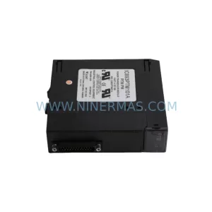
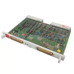
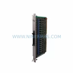
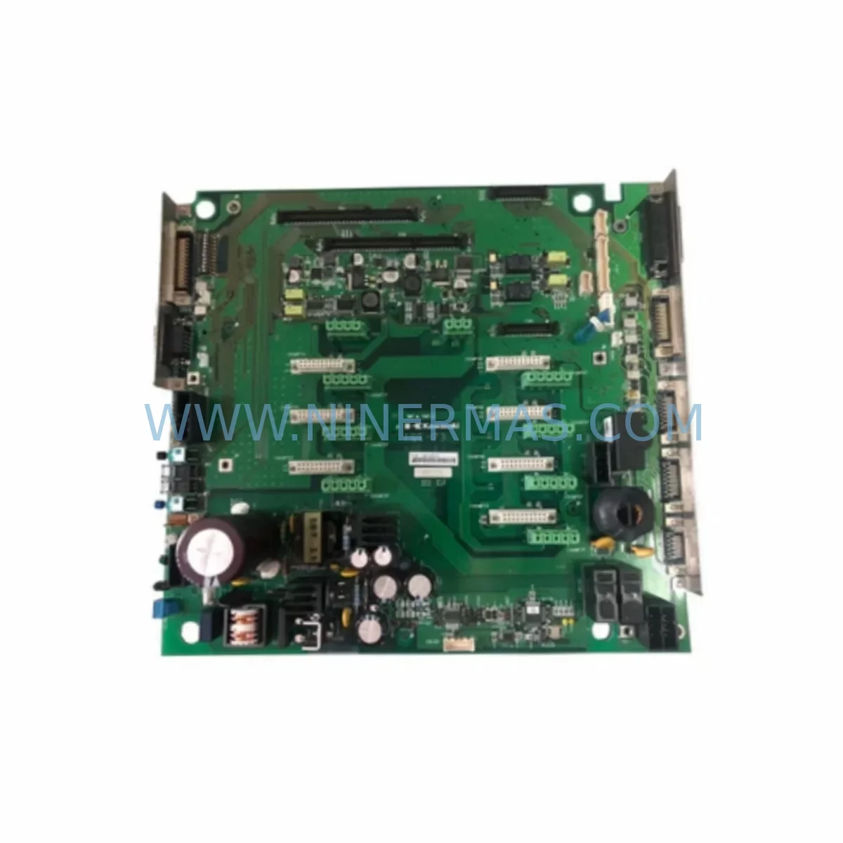
Kawasaki 50999-2728 Retrofit-Compatible Base Board for Legacy Systems
Verify the part, confirm the platform family, and move straight into quotation with the right commercial details.
RFQ Ready
- SKU50999-2728 1QE-73 1QE-13 1QE-83
- CategoryPLC & Industrial Automation Modules
- BrandKawasaki
- SupportAvailability, lead time, condition, and shipping coordination
How Buyers Usually Use This Page
- Confirm the exact part number and platform family before sending the quote request.
- Use direct email when quantity, condition, and destination are already defined internally.
- Switch to the broader brand or category archive when you need alternates nearby.
Series Navigation
Move through the most common platform families behind this part.
Product RFQ
Send this part directly for quotation.
Include quantity, required condition, destination country, and target delivery timing. Current reference: Kawasaki 50999-2728 Retrofit-Compatible Base Board for Legacy Systems with SKU 50999-2728 1QE-73 1QE-13 1QE-83.
Kawasaki 50999-2728 Retrofit-Compatible Base Board Module for Legacy Robot Controller Systems
The Kawasaki 50999-2728 — covering part variants 1QE-73, 1QE-13, and 1QE-83 — is a ruggedized base board module engineered for Kawasaki industrial robot controllers. Designed to serve as the central backplane interface within the controller cabinet, this module provides the structural and electrical foundation for CPU boards, I/O expansion cards, servo amplifier communication links, and inter-board signal routing. As Kawasaki progressively phases out legacy D-series and E-series controller platforms, the 50999-2728 base board has become a critical retrofit and replacement component for automation engineers tasked with extending the operational life of existing robotic cells without full system replacement.
For plants running Kawasaki robots on aging controller hardware — particularly those using the D60, D65, E60, or E62 controller generations — sourcing a verified replacement base board is often the difference between a controlled maintenance window and an unplanned production stoppage. The 50999-2728 module supports the backplane slot architecture used across multiple Kawasaki controller families, making it a high-priority spare for any facility maintaining a fleet of Kawasaki articulated or SCARA robots.
Upgrade Compatibility Table
| Parameter | Details |
|---|---|
| Part Number | 50999-2728 (Variants: 1QE-73 / 1QE-13 / 1QE-83) |
| Brand | Kawasaki |
| Module Type | Ruggedized Base Board / Backplane Module |
| Compatible Controller Platforms | Kawasaki D-series (D60, D65), E-series (E60, E62) robot controllers |
| Mounting / Installation | Direct backplane slot installation within Kawasaki controller cabinet |
| Interface Compatibility | CPU board, servo amplifier I/F board, I/O expansion modules, teach pendant communication |
| Communication Protocol Support | Internal Kawasaki proprietary bus; compatible with DeviceNet and CC-Link I/O expansion configurations |
| Replacement Recommendation | Direct replacement for failed or end-of-life 50999-2728 base boards; verify variant suffix (1QE-73 / 1QE-13 / 1QE-83) against controller BOM |
| Commissioning Notes | Re-seat all daughter boards after installation; verify slot addressing and re-run controller self-diagnostic; confirm teach pendant communication link |
| Warranty | 12 Months — covers manufacturing defects and functional failure under normal operating conditions |
Retrofit Planning for Existing Automation Systems
Replacing the 50999-2728 base board is rarely an isolated task. In most retrofit scenarios, the base board failure or degradation is symptomatic of broader controller aging, and a structured replacement plan significantly reduces the risk of secondary failures during or after the maintenance window.
Before removing the existing base board, engineers should document the full slot population of the controller cabinet. Typical Kawasaki D/E-series controllers house a CPU main board (such as the 50999-2001 or equivalent), a servo amplifier interface board, one or more I/O expansion boards for digital input/output signal routing, and a teach pendant interface card. Each of these daughter boards connects to the base board via edge connectors and ribbon cables — all of which must be inspected for corrosion, pin damage, or fatigue cracking before reinstallation on the new base board.
Power supply integrity is equally critical. The Kawasaki controller’s internal DC power supply unit feeds regulated voltages to the base board’s distribution rails. Before installing the 50999-2728 replacement, verify that the PSU output voltages (typically +5V, +12V, +24V DC) are within specification under load. An aging or marginal power supply can cause intermittent faults on a new base board that are difficult to diagnose without a known-good power reference.
For facilities that have integrated Kawasaki robots into broader PLC-based automation architectures — for example, using a Mitsubishi MELSEC Q-series or Siemens S7-300 as the line controller — the robot controller’s DeviceNet slave module or CC-Link communication card must be re-verified after base board replacement. Communication node addresses, baud rate settings, and I/O mapping tables should be confirmed against the original network configuration documentation before resuming production.
If the robot cell includes a Kawasaki OP3 or OP5 operator panel, or interfaces with a third-party HMI terminal via RS-232 or Ethernet, the communication link parameters (IP address, port, baud rate) should be re-confirmed after controller restart. Base board replacement can occasionally reset non-volatile memory segments depending on battery backup status — always verify battery condition on the CPU board before and after the swap.
For multi-robot cells where the Kawasaki controller communicates with a signal isolator module or safety relay board for E-stop and zone interlock circuits, the safety circuit continuity must be verified with a dedicated test sequence before returning the cell to automatic mode. Do not bypass safety interlocks during commissioning, even temporarily.
In cases where the retrofit is part of a broader control system modernization — migrating from the legacy Kawasaki D-series platform to a current-generation Kawasaki F-series or E-series successor controller — the 50999-2728 base board replacement may serve as an interim measure to stabilize the existing system while the full migration is planned and budgeted. This approach is common in facilities where robot program libraries are extensive and re-teaching or re-simulation is not immediately feasible.
Programming cable availability should also be confirmed. The Kawasaki programming cable (USB or RS-232 to teach pendant port) is required for any parameter backup, program upload, or diagnostic session following base board replacement. Ensure a verified cable and compatible AS language programming software version are available on-site before beginning the swap.
Downtime Control During System Migration
Minimizing unplanned downtime during a base board replacement requires preparation that begins well before the maintenance window opens. The following approach is recommended for facilities where robot uptime is directly tied to production throughput:
Pre-maintenance backup: Use the Kawasaki teach pendant or AS language programming interface to perform a full backup of all robot programs, system parameters, tool data, and I/O assignments to an external storage device. Confirm the backup is readable and complete before proceeding. If the controller’s battery-backed RAM is suspect, perform the backup immediately — do not wait until the maintenance window.
Slot mapping documentation: Photograph or diagram the exact position of every board installed in the controller cabinet before removal. Note cable routing, connector orientation, and any field-applied labels. This documentation is invaluable if a board is inadvertently reseated in the wrong slot during reassembly.
Staged replacement: Where possible, bench-test the replacement 50999-2728 base board with a known-good CPU board and power supply before installing it in the production controller. This confirms the replacement unit is functional and eliminates the base board as a variable if post-installation faults occur.
Post-installation verification sequence: After installation, power up the controller in maintenance mode, run the built-in self-diagnostic, verify all slot boards are recognized, restore the program backup, and perform a slow-speed dry-run of the robot program before returning to full automatic operation. Confirm all I/O signals, safety interlocks, and communication links are active and correct before releasing the cell to production.
By following this structured approach, most Kawasaki base board replacements can be completed within a single planned maintenance shift, with the robot cell returning to full production capability at the end of the window.
Retrofit Support FAQ
Q: Is the Kawasaki 50999-2728 a direct drop-in replacement for all three variants (1QE-73, 1QE-13, 1QE-83)?
A: The three variant suffixes reflect minor hardware revisions or regional build specifications within the same base board family. In most retrofit applications, the variants are functionally interchangeable within the same controller generation. However, always cross-reference the variant suffix against your controller’s bill of materials or service manual before ordering to confirm compatibility with your specific cabinet configuration.
Q: What commissioning steps are required after installing the replacement base board?
A: After physical installation and cable reconnection, power up the controller in diagnostic mode and run the full self-test sequence. Verify that all installed daughter boards (CPU, servo I/F, I/O expansion) are recognized in the slot map. Restore the pre-maintenance program and parameter backup via the teach pendant. Perform a slow-speed test cycle of the robot program with safety gates closed before returning to automatic production mode.
Q: How is the 50999-2728 tested before shipment?
A: Each unit undergoes functional verification prior to dispatch, including power rail continuity checks, slot connector integrity inspection, and where applicable, powered board-level testing. Units are shipped with protective packaging to prevent ESD damage and physical connector damage in transit. A 12-month warranty covers manufacturing defects and functional failure under normal operating conditions from the date of receipt.
Q: What is the typical lead time and stock availability for the Kawasaki 50999-2728?
A: Stock availability varies based on current inventory levels. Contact our team directly for real-time stock confirmation and lead time. For facilities with critical uptime requirements, we recommend confirming availability and placing orders in advance of the planned maintenance window rather than waiting for a failure event. Our team can advise on recommended spare holding quantities based on your robot fleet size and controller age profile.
—
| Product Series | Legacy |
|---|
Catalog Continuation
More Kawasaki modules in the catalog.
Use the brand lane to compare nearby part numbers, platform-adjacent modules, and other inquiry-ready listings before sending your final RFQ.
SKU: 50999-2254 50999-0020 50999-1692
Kawasaki 50999-2254 Safety-Reliable PLC Board for Critical Sites
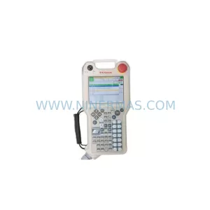
SKU: 50817-0096L05 R2AA06020FCPPJ 50601-1462
Kawasaki 50817-0096L05 Safety-Reliable Pendant for Critical Sites
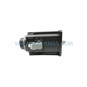
SKU: AVR50630-0033 50632-1066 R2AA13200LCPKZ
Kawasaki AVR50630-0033 Safety-Reliable AC Servo for Critical Sites
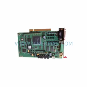
SKU: 50607-1273 50607-1273 50999-1950R00
Kawasaki 50607-1273 Safety-Reliable Robot Controller for Critical Sites
Catalog Continuation
Alternative parts within PLC & Industrial Automation Modules.
Stay inside the same system family when you need substitutes, adjacent modules, or a broader shortlist for procurement review.
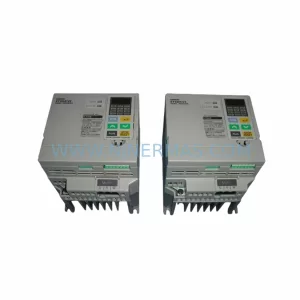
SKU: 3G3EV-AB007M-E
OMRON 3G3EV-AB007M-E Retrofit-Compatible VFD for Legacy Systems
SKU: 2711P-RDT15C SER B
Allen-Bradley 2711P-RDT15C SER B Industrial Spare Part