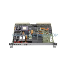
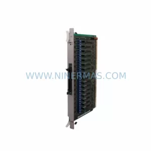
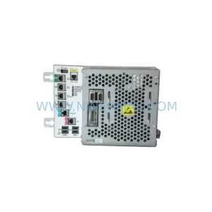
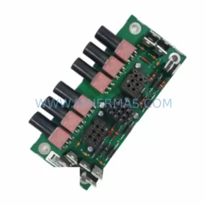
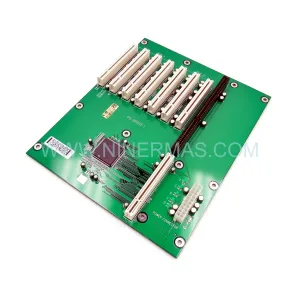
Original Industrial Spare Part
Kawasaki 50817-0128L05 Retrofit-Compatible Display for Legacy Systems
Verify the part, confirm the platform family, and move straight into quotation with the right commercial details.
RFQ Ready
- SKU50817-0128L05
- CategoryPLC & Industrial Automation Modules
- BrandKawasaki
- SupportAvailability, lead time, condition, and shipping coordination
How Buyers Usually Use This Page
- Confirm the exact part number and platform family before sending the quote request.
- Use direct email when quantity, condition, and destination are already defined internally.
- Switch to the broader brand or category archive when you need alternates nearby.
Series Navigation
Move through the most common platform families behind this part.
Product RFQ
Send this part directly for quotation.
Include quantity, required condition, destination country, and target delivery timing. Current reference: Kawasaki 50817-0128L05 Retrofit-Compatible Display for Legacy Systems with SKU 50817-0128L05.
Kawasaki 50817-0128L05 Retrofit-Compatible Display for Legacy Systems: Seamless Legacy System Integration and Smooth Upgrade
The Kawasaki 50817-0128L05 is a retrofit-compatible industrial screen display module designed to serve as a direct replacement for end-of-life and discontinued display units within Kawasaki robot controller platforms. As manufacturing facilities face increasing pressure to extend the operational life of legacy automation lines, sourcing a verified, pre-tested display replacement becomes critical to maintaining production continuity. The 50817-0128L05 addresses this need by offering a compatible interface footprint, matching backplane connector layout, and validated signal compatibility with the original Kawasaki controller architecture.
Before proceeding with a display replacement, engineers must confirm several key parameters: the power supply voltage rail feeding the display (typically 24VDC from the controller’s internal power supply module), the connector type and pin-out on the backplane interface, the display resolution and signal format expected by the CPU module, and whether the existing HMI screen program references any display-specific memory addresses that may require remapping. In many Kawasaki controller cabinets, the display module communicates directly with the main CPU board via a dedicated internal bus, meaning any replacement must maintain the same communication protocol and timing characteristics to avoid program faults or screen initialization errors.
System integrators working on Kawasaki robot controller retrofits will often encounter the need to simultaneously address related components. The Kawasaki 50999-0037R10 CPU module, for example, must be confirmed compatible with the replacement display’s interface protocol before installation. Similarly, the backplane or rack assembly — such as the Kawasaki 50999-0022R10 — must be inspected for physical damage or oxidized connector pins that could cause intermittent display faults even after a successful module swap. In controller cabinets where the Kawasaki 50607-0167 power supply module is aging, it is advisable to verify output voltage stability under load before commissioning the new display, as voltage sag can cause display initialization failures that are easily misdiagnosed as module defects.
Upgrade Compatibility Table
| Parameter | Original Unit | 50817-0128L05 Replacement | Notes |
|---|---|---|---|
| Interface Type | Proprietary Kawasaki backplane bus | Compatible proprietary bus | Verify connector pin-out before installation |
| Power Input | 24VDC from internal PSU | 24VDC | Confirm PSU output stability (Kawasaki 50607-0167) |
| Display Resolution | Model-dependent | Matched to original spec | Confirm with controller CPU firmware version |
| Communication Protocol | Internal controller bus | Compatible | No protocol migration required |
| Physical Mounting | Standard Kawasaki panel mount | Direct fit | Confirm cabinet cutout dimensions |
| HMI Screen Program | Existing program retained | Compatible | Backup program before swap; verify screen address mapping |
| Commissioning Focus | — | Power-on test, display init, HMI navigation check | Test all operator screens post-installation |
| Warranty | — | 12-Month Warranty | Covered by NINERMAS from shipment date |
Retrofit Planning for Existing Automation Systems
A successful display retrofit within a Kawasaki robot controller system requires a structured approach that accounts for the interdependencies between the display module and surrounding components. The 50817-0128L05 is typically installed in controller cabinets alongside a range of modules that must be assessed as part of the overall retrofit plan.
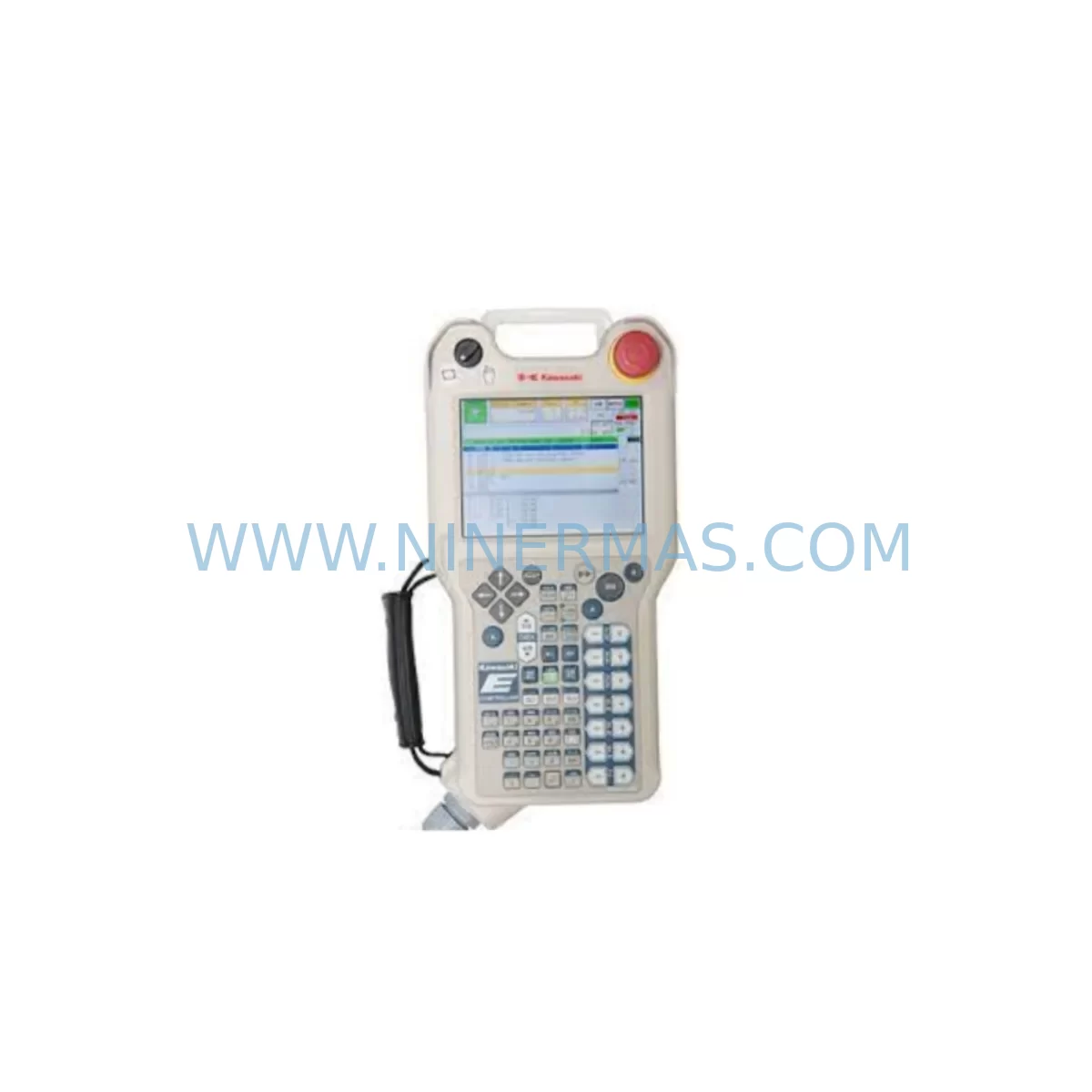
The teach pendant — such as the Kawasaki 1AS-52 — connects to the controller via a dedicated port and relies on the display module for operator feedback during manual jogging and program editing. Before replacing the display, confirm that the teach pendant cable and connector are in good condition, as a faulty pendant connection can generate display errors that are unrelated to the display module itself. In systems where the Kawasaki 50607-0223 servo drive amplifier is also being serviced, coordinate the display replacement with the drive commissioning sequence to minimize total downtime.
For I/O-intensive applications, the controller’s I/O expansion modules — including digital input/output boards mounted on the same rack as the display — must be verified for address continuity after the display swap. The Kawasaki 50607-0225 servo amplifier board, if present in the same cabinet, should be checked for firmware compatibility with the controller CPU to avoid communication faults that could be incorrectly attributed to the new display module. Communication modules such as the Kawasaki 50999-0038R10 handle fieldbus or Ethernet connectivity and should be tested independently to confirm that the display replacement has not affected network communication paths.
In older Kawasaki controller installations, the Kawasaki 50817-0093 display panel may have been the original unit in service. When replacing this with the 50817-0128L05, engineers should document the original wiring layout, photograph the connector positions, and label all cables before disconnection. This documentation reduces the risk of wiring errors during reassembly and supports faster fault diagnosis if issues arise during commissioning. Installation space within the controller cabinet should be measured carefully, as even minor dimensional differences between the original and replacement display can affect panel fitment and door closure.
Downtime Control During System Migration
Minimizing unplanned downtime is the primary concern for maintenance teams replacing a display module in an active production environment. The 50817-0128L05 replacement process should be planned during a scheduled maintenance window, with all replacement parts — including the display module, spare connector pins, and any required mounting hardware — staged and verified before the controller is powered down.
Prior to shutdown, the existing robot program should be backed up to an external storage device using the teach pendant or the controller’s program export function. This backup protects against data loss in the event that the CPU module loses program memory during the power cycle. The HMI screen configuration, including any custom operator screens or alarm displays, should also be exported and stored separately.
During the replacement, the controller should remain powered down for the minimum time necessary to complete the physical swap and initial wiring verification. Once the 50817-0128L05 is installed and connectors are secured, a controlled power-on sequence should be followed: first verify the power supply output voltage, then power on the controller and observe the display initialization sequence. If the display fails to initialize, check the backplane connector seating before assuming a module fault. After successful initialization, navigate through all HMI screens to confirm that the display is rendering correctly and that all operator controls are responsive. A full cycle test of the robot program should be completed before returning the system to production.
For facilities managing multiple Kawasaki controller cabinets, a phased replacement approach — addressing one cabinet at a time — reduces the risk of simultaneous downtime across multiple production cells. Maintaining a spare 50817-0128L05 unit in local inventory further reduces mean time to repair (MTTR) for future display failures.
Retrofit Support FAQ
Q1: Is the Kawasaki 50817-0128L05 a direct replacement for the original display in my controller?
A: The 50817-0128L05 is designed as a retrofit-compatible replacement for the original Kawasaki display module in compatible controller platforms. Before installation, confirm the backplane connector type, power input voltage, and controller firmware version to ensure full compatibility. NINERMAS provides pre-shipment compatibility verification upon request.
Q2: What pre-shipment testing is performed on the 50817-0128L05?
A: Each unit undergoes functional power-on testing and display initialization verification before shipment. NINERMAS issues a test report confirming the module’s operational status. All units are covered by a 12-month warranty from the date of shipment, covering manufacturing defects and functional failures under normal operating conditions.
Q3: How do I confirm wiring compatibility before installing the replacement display?
A: Compare the connector pin-out of the 50817-0128L05 with the original unit using the Kawasaki controller wiring diagram for your specific model. Pay particular attention to the power input pins, signal lines, and any ground connections. If the original wiring diagram is unavailable, NINERMAS technical support can assist with pin-out verification based on the controller model and serial number.
Q4: What is the stock availability and lead time for the Kawasaki 50817-0128L05?
A: NINERMAS maintains ready stock of the 50817-0128L05 to support urgent replacement requirements. Standard lead time for in-stock units is 3–7 business days for international shipment. For large-quantity orders or reserved inventory agreements, contact NINERMAS to discuss long-term supply arrangements and pricing.
| Product Series | Legacy |
|---|
Catalog Continuation
More Kawasaki modules in the catalog.
Use the brand lane to compare nearby part numbers, platform-adjacent modules, and other inquiry-ready listings before sending your final RFQ.
SKU: 50817-0096L05 R2AA06020FCPPJ 50601-1462
Kawasaki 50817-0096L05 Safety-Reliable Pendant for Critical Sites
SKU: AVR50630-0033 50632-1066 R2AA13200LCPKZ
Kawasaki AVR50630-0033 Safety-Reliable AC Servo for Critical Sites
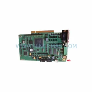
SKU: 50607-1273 50607-1273 50999-1950R00
Kawasaki 50607-1273 Safety-Reliable Robot Controller for Critical Sites
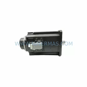
SKU: 50601-1460/R2AA13200LCP2S
Kawasaki 50601-1460 Retrofit Servo Motor for Legacy Systems
Catalog Continuation
Alternative parts within PLC & Industrial Automation Modules.
Stay inside the same system family when you need substitutes, adjacent modules, or a broader shortlist for procurement review.
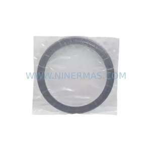
SKU: PVD300 17-307113-00 2301407-B SM2315D-BRK 02-306362-00
Novellus 307113-00 Service-Ready Spare Part for Maintenance
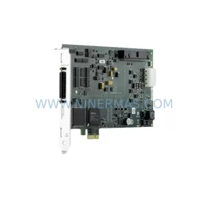
SKU: 3152225-035A MDX-10K AP1415S 2PW MVE4 MVE4 P 23020202-B
Advanced Energy 3152225-035A Retrofit-Compatible RF Generator