Description
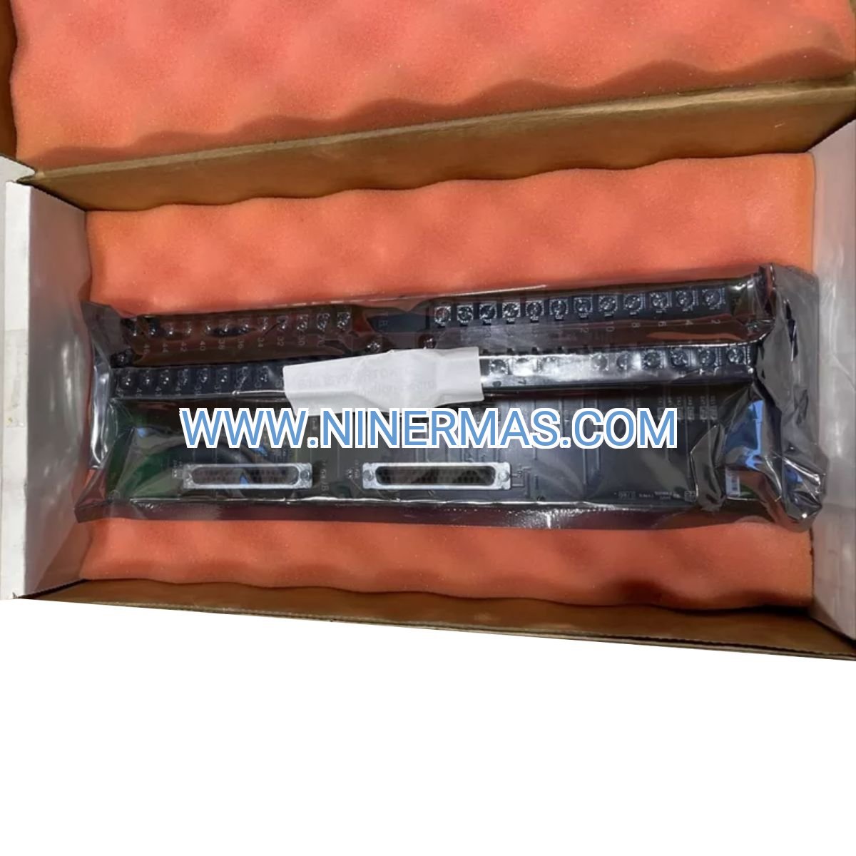
IS200TRDH1CCC Relay Driver Terminal Board for Mark VI Turbine Control Systems
The GE IS200TRDH1CCC is an industrial-grade relay driver terminal board engineered for Mark VI turbine control platforms. Through precision relay driver circuitry and VME bus integration, it delivers reliable discrete signal control for external device actuation in power generation, oil & gas, and industrial turbine applications.
Designed for critical control environments where uptime and signal integrity are paramount, this board addresses common challenges including relay contact degradation, signal isolation failures, and diagnostic visibility gaps. It serves turbine OEMs, power plant operators, system integrators, and maintenance teams requiring proven Mark VI-compatible I/O expansion.
Featuring 12 independent relay outputs with LED status indication, VME backplane connectivity, and comprehensive fault reporting, the IS200TRDH1CCC combines field-proven reliability with straightforward integration. Suitable for new installations and retrofit projects, it supports both 24 VDC and 125 VDC external control circuits. Contact our application engineers for system compatibility verification and technical documentation.
Core Features & Technical Advantages
12-Channel Relay Output Architecture
Provides twelve independent dry contact relay outputs (typically rated for 24 VDC or 125 VDC circuits), enabling direct control of solenoid valves, contactors, annunciators, and auxiliary equipment without additional interface modules.
Mark VI System Integration
Seamless VME bus communication with Mark VI control processors ensures deterministic response times and synchronized operation with turbine protection logic, reducing commissioning complexity and system latency.
Enhanced Diagnostic Capability
Multi-color LED indicators for power status, relay state, and fault conditions provide immediate visual feedback, while integrated diagnostics report relay coil failures and wiring faults to the supervisory control system for predictive maintenance.
Industrial Environmental Resilience
Operates reliably across -30°C to +65°C ambient temperatures with 5-95% non-condensing humidity tolerance, meeting the demanding conditions of turbine enclosures, generator halls, and outdoor control cabinets.
Signal Isolation & Protection
Internal optical isolation between control logic and relay drivers prevents ground loops and electrical noise propagation, protecting sensitive Mark VI processors from field-side transients and improving overall system EMC performance.
Simplified Installation & Maintenance
Plug-in VME card design with keyed connectors and clearly labeled terminal blocks accelerates installation, while hot-swap capability (when properly configured) minimizes downtime during board replacement procedures.
Typical Application Scenarios
This relay driver board is optimized for discrete output control in systems requiring high reliability and deterministic performance, particularly in:
Gas & Steam Turbine Control Systems
Controls fuel valve actuators, lube oil pump starters, cooling water valves, and emergency shutdown devices in combined-cycle plants, cogeneration facilities, and mechanical drive applications where Mark VI serves as the primary control platform.
Power Generation Auxiliary Systems
Manages generator breaker trip circuits, excitation system interlocks, cooling fan sequencing, and fire suppression system activation in utility-scale power plants, ensuring coordinated operation between turbine control and balance-of-plant equipment.
Compressor & Pump Control Packages
Provides discrete outputs for anti-surge valve control, recycle valve positioning, motor starter permissives, and vibration trip relays in pipeline compressor stations, LNG facilities, and petrochemical process units utilizing Mark VI-based control architectures.
Retrofit & Modernization Projects
Enables expansion of existing Mark VI I/O capacity during plant upgrades, control system migrations from legacy platforms, or addition of new safety interlocks without requiring controller hardware changes, preserving capital investment in proven control infrastructure.
Technical Specifications & Selection Guide
To facilitate engineering design and procurement, we provide comprehensive technical parameters for the IS200TRDH1CCC. Custom configurations and application-specific validation are available upon request.
| Parameter | Specification |
|---|---|
| Manufacturer | General Electric (GE) |
| Control Platform | Mark VI Turbine Control System |
| Part Number | IS200TRDH1CCC |
| Board Type | Relay Driver Terminal Board |
| Relay Outputs | 12 channels (dry contact, Form C) |
| Contact Rating | Typically 24 VDC / 125 VDC (verify for specific application) |
| Input Signals | Digital control commands via VME backplane |
| Communication Interface | VME bus (Mark VI system backplane) |
| Status Indication | LED indicators (power, relay state, diagnostics) |
| Redundancy | Simplex (non-redundant configuration) |
| Power Supply | 5 VDC, 24 VDC from VME backplane + external relay power |
| Power Consumption | ≤6 W (excluding external relay loads) |
| Operating Temperature | -30°C to +65°C |
| Storage Temperature | -40°C to +85°C |
| Humidity Range | 5% to 95% RH (non-condensing) |
| Enclosure Rating | IP20 (cabinet-mounted) |
| Dimensions (H×W×D) | Approx. 233 mm × 160 mm × 40 mm |
| Weight | 0.6 kg |
| Mounting | VME rack plug-in (keyed connectors) |
| Certifications | CE, UL, cULus, RoHS compliant |
Selection Considerations
When specifying the IS200TRDH1CCC, engineering teams should verify: (1) Mark VI controller firmware compatibility and available VME slot positions, (2) external relay power supply voltage and current capacity, (3) field device contact ratings and inductive load suppression requirements, (4) environmental conditions including temperature extremes and vibration levels, (5) spare I/O capacity for future expansion. Our application engineers can review system architecture drawings and provide integration recommendations—submit your Mark VI configuration details and I/O list for personalized technical guidance.
Extended Capabilities & System Integration
Flexible Output Configuration
Relay outputs can be field-configured for normally-open (NO) or normally-closed (NC) operation, supporting both energize-to-trip and de-energize-to-trip safety logic philosophies. Terminal blocks accept 14-22 AWG wire for robust field connections.
Diagnostic Data Integration
Fault status and relay health data integrate with Mark VI HMI and SCADA systems via standard communication protocols, enabling centralized alarm management and maintenance scheduling based on relay cycle counts and contact wear prediction.
Compliance & Documentation
Supplied with complete technical documentation including electrical schematics, terminal wiring diagrams, VME backplane pinouts, and configuration procedures. Meets international standards for industrial control equipment (IEC 61131, NEMA ICS) and electromagnetic compatibility (EN 61000 series).
Delivery, Service & Quality Assurance
Stock Availability & Lead Time
Standard IS200TRDH1CCC boards typically ship within 3-7 business days from our logistics centers. Custom-tested or pre-configured units (firmware verification, burn-in testing) require 10-15 business days. Expedited shipping options available for critical outage support.
Warranty & Technical Support
All boards include a minimum 12-month warranty covering manufacturing defects and component failures. Comprehensive technical support includes pre-sales application consulting, installation guidance, troubleshooting assistance, and access to firmware updates. On-site commissioning support available in select regions (quoted separately).
Documentation Package
Each shipment includes: (1) Product datasheet with electrical specifications, (2) Installation and wiring guide with terminal diagrams, (3) VME backplane integration instructions, (4) LED diagnostic code reference, (5) Recommended spare parts list. CAD drawings and 3D STEP models available upon request for panel design integration.
Quality & Traceability
Every board undergoes functional testing and quality inspection prior to shipment. Serialized units with full traceability documentation available for projects requiring material certifications, calibration records, or compliance with nuclear/aerospace quality standards (ASME NQA-1, AS9100).
Frequently Asked Questions (FAQ)
Q: How does the IS200TRDH1CCC relay driver board integrate with existing Mark VI control systems?
A: The board installs directly into an available VME slot in your Mark VI rack and communicates via the system backplane—no additional interface cards required. Configuration is performed through standard Mark VI ToolboxST software. Verify VME slot availability and controller I/O capacity before ordering; our team can review your system configuration to confirm compatibility.
Q: What is the maximum number of relay outputs I can control with one IS200TRDH1CCC board?
A: Each board provides 12 independent relay outputs. For applications requiring more than 12 discrete outputs, multiple IS200TRDH1CCC boards can be installed in the same VME rack, subject to backplane power budget and slot availability. Typical Mark VI racks support 4-8 I/O boards depending on configuration.
Q: Can this relay driver board be used in safety-instrumented systems (SIS) or emergency shutdown applications?
A: The IS200TRDH1CCC is designed for standard turbine control applications. For SIS applications requiring SIL-rated components, consult GE's safety system product line or contact our engineering team to discuss certified alternatives and functional safety compliance requirements per IEC 61508/61511.
Q: What are the environmental protection requirements for installation?
A: The board carries an IP20 rating and must be installed inside a properly rated control cabinet (typically NEMA 12 or IP54 minimum). Ensure adequate ventilation to maintain ambient temperature within -30°C to +65°C, and protect against condensation, corrosive gases, and excessive vibration. For harsh environments, consider cabinet air conditioning or purge systems.
Q: Does the IS200TRDH1CCC support remote monitoring and predictive maintenance capabilities?
A: Yes—relay status, fault codes, and diagnostic data are accessible through the Mark VI control network and can be integrated with plant SCADA, DCS, or condition monitoring systems via Modbus TCP, OPC UA, or proprietary GE protocols. This enables remote troubleshooting, relay cycle tracking, and predictive replacement scheduling.
Q: What technical information do I need to provide for application support and quotation?
A: Please supply: (1) Mark VI controller model and firmware version, (2) Number of relay outputs required and contact voltage/current ratings, (3) Field device types being controlled (solenoid valves, contactors, etc.), (4) Environmental conditions (temperature range, enclosure type), (5) Project timeline and quantity requirements. Our application engineers will provide tailored recommendations and formal quotations within 24-48 hours.
Request Technical Consultation & Quotation
For detailed application engineering support, system integration guidance, or project-specific quotations, please provide the following information to our technical sales team:
- Project name and application overview (turbine type, plant capacity, control objectives)
- Mark VI system configuration (controller model, firmware version, existing I/O complement)
- Required relay outputs (quantity, contact ratings, controlled device types)
- Environmental parameters (ambient temperature range, enclosure specifications, altitude)
- Delivery timeline and quantity requirements (single unit, spares package, or multi-site rollout)
- Documentation needs (material certifications, test reports, compliance declarations)
Our certified Mark VI specialists will respond with customized recommendations, compatibility verification, and competitive pricing within one business day.
© 2026 NINERMAS COMPANY LIMITED. All rights reserved.
Original Source: https://ninermas.com
Contact: sale@ninermas.com | +0086 187 5021 5667


Contact Info
-
Address:22 / F, South Wo Hang building, 148 Wing Lok Street, Sheung Wan, Western District, Hong Kong
-
Phone:+8618750215667
-
Email: