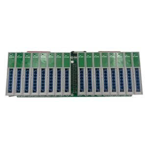
Original Industrial Spare Part
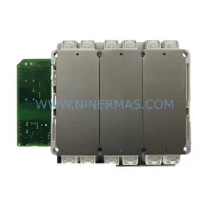
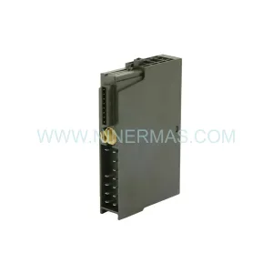
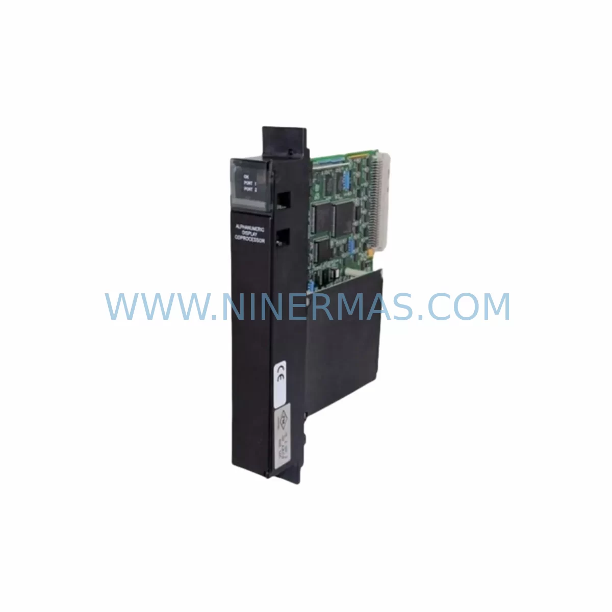
GE IC697ADC701 Retrofit-Compatible Analog Output Module
Verify the part, confirm the platform family, and move straight into quotation with the right commercial details.
RFQ Ready
- SKUIC697ADC701
- CategoryPLC & Industrial Automation Modules
- BrandGE
- SupportAvailability, lead time, condition, and shipping coordination
How Buyers Usually Use This Page
- Confirm the exact part number and platform family before sending the quote request.
- Use direct email when quantity, condition, and destination are already defined internally.
- Switch to the broader brand or category archive when you need alternates nearby.
Series Navigation
Move through the most common platform families behind this part.
Product RFQ
Send this part directly for quotation.
Include quantity, required condition, destination country, and target delivery timing. Current reference: GE IC697ADC701 Retrofit-Compatible Analog Output Module with SKU IC697ADC701.
GE IC697ADC701 Retrofit-Compatible Analog Output Module for Legacy Series 90-70 Systems
The GE IC697ADC701 is a ruggedized analog output module designed for the GE Series 90-70 programmable logic controller platform — one of the most widely deployed industrial control architectures in process manufacturing, power generation, and discrete automation. As GE Automation (now part of Emerson) has progressively discontinued support for the Series 90-70 product line, the IC697ADC701 has become a critical spare part for facilities seeking to extend the operational life of existing control systems without undertaking a full DCS or PLC migration.
This module delivers precision analog output signals compatible with the IC697 backplane architecture, making it a direct drop-in replacement for failed or end-of-life units in existing control cabinets. Whether your facility is managing a phased retrofit, responding to an unplanned module failure, or building a long-term spare parts inventory program, the IC697ADC701 provides the signal integrity and mechanical compatibility required for seamless reintegration into your existing automation infrastructure.
Upgrade Compatibility Table
| Parameter | Details |
|---|---|
| Module SKU | IC697ADC701 |
| Platform | GE Series 90-70 (IC697 family) |
| Module Type | Analog Output |
| Backplane Interface | IC697 VME-based backplane (compatible with IC697CHS750, IC697CHS782, IC697CHS790) |
| Signal Range | 4–20 mA / 0–10 VDC (configurable per channel) |
| Output Channels | 8 channels |
| Installation Requirement | Slot-compatible with IC697 rack; no hardware modification required |
| Communication Compatibility | Compatible with IC697CMM711, IC697CMM741 (Genius Bus, Ethernet TCP/IP) |
| Replacement Recommendation | Direct replacement for failed IC697ADC701 units; verify slot address and I/O configuration in Logicmaster 90 or Proficy Machine Edition |
| Commissioning Notes | Confirm module slot reference, analog scaling parameters, and loop power supply before hot-swap or cold-swap installation |
| Warranty | 12 months from shipment date — covers manufacturing defects and functional failure under normal operating conditions |
Retrofit Planning for Existing Automation Systems
Integrating the IC697ADC701 into an existing Series 90-70 control system requires a structured approach to ensure signal continuity and minimize disruption to ongoing production. The retrofit process typically begins with a full audit of the existing rack configuration — identifying the chassis model (commonly the IC697CHS750 or IC697CHS790), the slot assignment of the failed or aging analog output module, and the current wiring termination at the field terminal assembly.
Field engineers should verify the loop power supply feeding the analog output channels. In many legacy installations, the IC697ADC701 shares a 24 VDC bus with adjacent I/O modules such as the IC697MDL340 discrete input module or the IC697MDL753 relay output module. Confirming that the power supply module — typically an IC697PWR711 or IC697PWR724 — has sufficient capacity to support the replacement module under full load is a mandatory pre-installation step.
Wiring termination at the field terminal block must be documented before removal of the original module. Analog output loops connected to control valves, variable frequency drives, or positioners are particularly sensitive to signal interruption. Engineers should record the terminal assignments for each of the eight output channels and verify continuity after reinstallation using a calibrated loop calibrator.
For facilities running Logicmaster 90 or Proficy Machine Edition as the programming environment, the module slot reference in the hardware configuration must match the physical slot position in the IC697 rack. If the replacement IC697ADC701 is installed in a different slot due to rack layout constraints, the I/O address map must be updated in the PLC program and downloaded to the IC697CPU772 or IC697CPU781 controller before resuming production. Failure to synchronize the hardware configuration with the physical installation is one of the most common causes of commissioning delays during analog module retrofits.
In systems where the Series 90-70 communicates with a supervisory SCADA or DCS layer via the IC697CMM711 Ethernet module or the IC697BEM711 Genius Bus Controller, engineers should confirm that the analog output tags mapped to the IC697ADC701 channels are correctly referenced in the communication configuration. HMI screens built on iFIX, CIMPLICITY, or third-party SCADA platforms should be reviewed to ensure that faceplate displays and trend historians continue to receive valid engineering-unit values after the module swap.
Where installation space is constrained — particularly in older control cabinets with limited airflow — thermal management should be assessed. The IC697ADC701 operates within the standard Series 90-70 thermal envelope, but adjacent modules such as the IC697ALG320 analog input module or high-density discrete modules may contribute to localized heat buildup. Ensuring adequate rack ventilation and verifying that the cabinet cooling system is functional before commissioning reduces the risk of thermal-related faults post-installation.
Downtime Control During System Migration
Minimizing unplanned downtime is the primary operational concern when replacing analog output modules in a live production environment. For facilities that cannot tolerate extended shutdowns, a cold-swap procedure — performed during a scheduled maintenance window — is strongly recommended over emergency hot-swap operations, which carry a higher risk of transient signal disturbances on connected field devices.
Before initiating the swap, the existing PLC program should be backed up from the IC697CPU772 or IC697CPU781 to a programming workstation running Proficy Machine Edition. This backup preserves the full logic program, hardware configuration, and analog scaling parameters, providing a recovery baseline in the event of an unexpected fault during commissioning. The backup file should be stored on a local drive and verified for completeness before the physical module is removed.
During the replacement window, analog output loops connected to critical control elements — such as flow control valves or pressure regulators — should be placed in manual mode at the field level or at the DCS/SCADA operator station. This prevents uncontrolled process excursions caused by loss of the 4–20 mA signal during the module changeover. Field operators should be briefed on the expected duration of the maintenance window and the procedure for returning loops to automatic control after commissioning is confirmed.
Post-installation verification should include a channel-by-channel output test using a calibrated milliamp meter or HART communicator to confirm that each of the eight analog output channels is producing the correct signal at the field terminal. The PLC program should be forced to output known engineering values — typically 0%, 50%, and 100% of the configured range — and the corresponding milliamp values verified at the terminal block. This functional test, combined with a review of the SCADA trend data for the first 30 minutes of operation, provides confidence that the IC697ADC701 replacement has been completed successfully and that production can resume without residual risk.
NINERMAS maintains in-stock inventory of the IC697ADC701 and related Series 90-70 components to support emergency and planned retrofit requirements. All units are pre-shipment tested under simulated load conditions and supplied with a 12-month warranty covering manufacturing defects and functional failure. Same-day dispatch is available for urgent requirements, with international shipping to manufacturing facilities across Asia, the Middle East, and Europe.
Retrofit Support FAQ
Q1: Is the IC697ADC701 a direct replacement for the original module in my Series 90-70 rack?
Yes. The IC697ADC701 is slot-compatible with all standard IC697 chassis models, including the IC697CHS750, IC697CHS782, and IC697CHS790. No hardware modification is required. The replacement module uses the same backplane connector and occupies the same single-slot footprint as the original unit. The only configuration step required is verifying that the slot address in the Logicmaster 90 or Proficy Machine Edition hardware configuration matches the physical installation slot.
Q2: Do I need to reconfigure my PLC program after installing the replacement IC697ADC701?
In most cases, no program changes are required if the replacement module is installed in the same slot as the original. The IC697 platform identifies modules by slot position, so a like-for-like replacement in the same slot will be recognized automatically by the IC697CPU772 or IC697CPU781 controller on the next power cycle. However, if the analog scaling parameters (engineering unit range, output type) were stored in the module’s local configuration rather than in the PLC program, these parameters should be re-entered and verified during commissioning.
Q3: What pre-shipment testing is performed on the IC697ADC701 before dispatch?
All IC697ADC701 units supplied by NINERMAS are functionally tested prior to shipment. Testing includes power-on verification, channel-by-channel analog output accuracy check across the full 4–20 mA and 0–10 VDC ranges, and backplane communication verification using a Series 90-70 test rack. Units that fail any test parameter are quarantined and not dispatched. A test report is available upon request for quality-critical applications.
Q4: What does the 12-month warranty cover, and what is the process for a warranty claim?
The 12-month warranty covers manufacturing defects and functional failure under normal operating conditions from the date of shipment. It does not cover damage caused by incorrect installation, overvoltage, reverse polarity, or physical impact. To initiate a warranty claim, contact NINERMAS at sale@ninermas.com with the order reference, a description of the fault, and photographic evidence of the installation. Replacement units are dispatched within 3–5 business days of claim approval, and failed units are returned to NINERMAS for failure analysis.
| Product Series | 90-70 |
|---|---|
| Country of Origin | US |
Catalog Continuation
More GE modules in the catalog.
Use the brand lane to compare nearby part numbers, platform-adjacent modules, and other inquiry-ready listings before sending your final RFQ.
Catalog Continuation
Alternative parts within PLC & Industrial Automation Modules.
Stay inside the same system family when you need substitutes, adjacent modules, or a broader shortlist for procurement review.
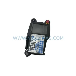
SKU: A05B-2518-C200
FANUC A05B-2518-C200 Retrofit Teach Pendant for Legacy Systems
SKU: 2711PC-T10C4D8
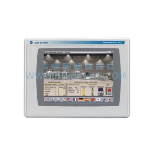
Allen-Bradley 2711PC-T10C4D8 Retrofit-Compatible HMI Terminal