Original Industrial Spare Part
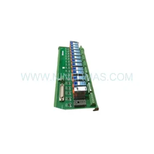
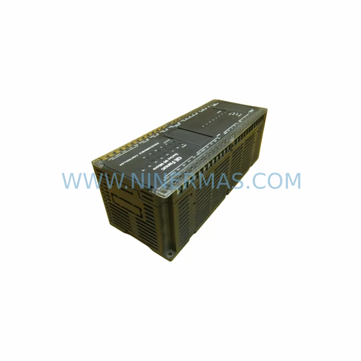
GE IC693UDR005EP1 Retrofit-Compatible Relay Output Module
Verify the part, confirm the platform family, and move straight into quotation with the right commercial details.
RFQ Ready
- SKUIC693UDR005EP1
- CategoryPLC & Industrial Automation Modules
- BrandGE Fanuc
- SupportAvailability, lead time, condition, and shipping coordination
How Buyers Usually Use This Page
- Confirm the exact part number and platform family before sending the quote request.
- Use direct email when quantity, condition, and destination are already defined internally.
- Switch to the broader brand or category archive when you need alternates nearby.
Series Navigation
Move through the most common platform families behind this part.
Product RFQ
Send this part directly for quotation.
Include quantity, required condition, destination country, and target delivery timing. Current reference: GE IC693UDR005EP1 Retrofit-Compatible Relay Output Module with SKU IC693UDR005EP1.
GE IC693UDR005EP1 Retrofit-Compatible Relay Output Module: Legacy System Compatibility & Smooth Upgrade
The GE Fanuc IC693UDR005EP1 is a ruggedized relay output module designed for the GE Series 90-30 PLC platform, one of the most widely deployed programmable logic controller families in industrial automation history. As production lines age and OEM support for legacy GE Fanuc hardware becomes increasingly limited, the IC693UDR005EP1 remains a critical component for engineers and maintenance teams tasked with keeping existing systems operational — or planning a controlled migration to modern control architectures.
NINERMAS supplies the IC693UDR005EP1 from verified inventory, fully tested prior to shipment, and backed by a 12-month warranty. Whether you are replacing a failed module on an active production line, building a spare parts buffer for a long-running system, or executing a phased retrofit of an aging control cabinet, this module provides the output capacity and environmental resilience required for demanding industrial environments.
Upgrade Compatibility Table
| Parameter | IC693UDR005EP1 Specification | Retrofit / Migration Notes |
|---|---|---|
| Platform | GE Series 90-30 | Direct slot-compatible with IC693CHS397, IC693CHS398, IC693CHS391 racks |
| Output Type | Relay (discrete) | Verify load current ratings before replacing transistor output modules (e.g. IC693MDL940) |
| Output Points | 16 relay outputs | Map I/O addresses in CPU (IC693CPU374, IC693CPU375) before hot-swap or cold replacement |
| Communication | Backplane bus (Series 90-30 native) | Compatible with IC693CMM321 (Ethernet), IC693CMM311 (SNP/SRTP) communication modules |
| Power Requirement | Supplied via backplane | Confirm IC693PWR321 or IC693PWR330 power supply capacity before adding modules |
| Installation Space | Single slot, standard 90-30 form factor | No mechanical modification required for same-rack replacement |
| Programming | Compatible with Proficy Machine Edition (ME) | Existing ladder logic and I/O table references remain valid; verify force lists are cleared |
| HMI Compatibility | Works with QuickPanel, CIMPLICITY, iFIX | HMI tag addresses unchanged when replacing like-for-like module in same slot |
| Warranty | 12 months from date of shipment — NINERMAS standard warranty | |
Retrofit Planning for Existing Automation Systems
Integrating the IC693UDR005EP1 into an existing Series 90-30 system requires a structured approach that accounts for both hardware compatibility and software configuration. The first step is confirming the rack configuration. The Series 90-30 platform supports multiple rack sizes — the IC693CHS397 (10-slot) and IC693CHS391 (5-slot) are the most common — and the replacement module must be installed in the same slot position as the original to preserve the I/O address mapping already programmed in the CPU.
Power budget verification is essential before any module swap. The IC693PWR321 and IC693PWR330 power supply modules each have defined backplane current limits. Adding or replacing relay output modules — which draw more backplane current than some solid-state alternatives — requires confirming that the total module load does not exceed the power supply’s rated output. Failure to verify this can result in intermittent faults or unexpected CPU resets during operation.
For systems that include communication modules such as the IC693CMM321 Ethernet Interface or the IC693CMM311 Serial Communications Module, the relay output module replacement does not affect network configuration or protocol settings. However, if the retrofit is part of a broader migration from a serial SNP/SRTP architecture to an Ethernet-based SRTP or Modbus TCP topology, the communication module upgrade should be planned as a separate, sequential step to avoid compounding variables during commissioning.
I/O expansion modules — including analog input modules such as the IC693ALG221 and analog output modules such as the IC693ALG390 — that share the same rack are unaffected by a relay output module replacement, provided slot assignments are maintained. Engineers should export and archive the current hardware configuration from Proficy Machine Edition before any physical change, creating a restore point that can be reloaded if commissioning reveals unexpected behavior.
Signal isolators installed between the relay output module and field devices — particularly in applications involving high-voltage loads, long cable runs, or electrically noisy environments — should be inspected and tested as part of the retrofit process. The IC693UDR005EP1’s relay contacts are rated for resistive and inductive loads, but the isolator’s input specifications must be matched to the relay’s output characteristics to ensure reliable signal transmission.
For systems using IC693MDL655 or similar discrete input modules on the same rack, the input module configuration and wiring remain unchanged during a relay output module replacement. This allows maintenance teams to isolate the output side of the control loop for testing without disrupting the input signal chain — a significant advantage when minimizing production downtime is a priority.
Programming cable access — typically via the IC690USB901 USB-to-serial programming cable or a direct RS-232 connection — should be confirmed before beginning the replacement procedure. Having an active connection to the CPU allows the technician to monitor I/O status in real time during commissioning and to force individual output points for field device verification without requiring full program execution.
Downtime Control During System Migration
Minimizing unplanned downtime is the primary operational concern when replacing output modules in a live production environment. The IC693UDR005EP1 replacement procedure is designed to be executed during a planned maintenance window, with the following sequence recommended to protect program logic and maintain control continuity.
Before powering down the rack, the technician should document all active output states, capture a full program backup from the CPU using Proficy Machine Edition, and verify that all field devices connected to the relay outputs are in a safe de-energized state. For processes where output de-energization triggers a safety interlock or process hold, coordination with the operations team is required before initiating the shutdown sequence.
The CPU — typically an IC693CPU374 or IC693CPU375 — retains the program in battery-backed RAM during a power cycle. Confirming that the CPU battery (IC693ACC301 or equivalent) is functional before the replacement procedure ensures that the program is preserved even if the power cycle extends beyond the expected duration. A failed battery discovered during a module replacement can extend the maintenance window significantly if a program reload from a programming device is required.
After installing the IC693UDR005EP1 and restoring power, the recommended commissioning sequence is: verify hardware configuration recognition in Proficy Machine Edition, confirm I/O table slot assignment matches the original configuration, force each output point individually to verify field device response, release all forces, and return the CPU to RUN mode. This structured approach allows the technician to identify any wiring discrepancy or address conflict before resuming automatic control, reducing the risk of a process fault on startup.
For systems where the relay output module drives critical actuators — valves, contactors, motor starters — a functional test under manual control before returning to automatic mode provides an additional layer of verification. The total commissioning time for a like-for-like IC693UDR005EP1 replacement in a well-documented system is typically 30 to 90 minutes, making it feasible within a standard shift maintenance window.
Retrofit Support FAQ
Q: Is the IC693UDR005EP1 a direct replacement for other GE Series 90-30 relay output modules?
A: Yes. The IC693UDR005EP1 is slot-compatible with other 16-point relay output modules in the Series 90-30 family. When replacing a module with the same point count and output type in the same slot, no hardware configuration changes are required in the CPU. If replacing a module with a different point count or output type (e.g., transistor to relay), the hardware configuration in Proficy Machine Edition must be updated and downloaded to the CPU before the new module will be recognized correctly.
Q: What pre-shipment testing does NINERMAS perform on the IC693UDR005EP1?
A: Each IC693UDR005EP1 unit supplied by NINERMAS undergoes functional testing that includes backplane communication verification, relay contact continuity testing on all 16 output points, and power-on self-diagnostic confirmation. Units that do not pass all test criteria are not shipped. A test report is available upon request for critical applications.
Q: How should I verify wiring compatibility before installing the replacement module?
A: Compare the terminal block wiring diagram of the original module with the IC693UDR005EP1 wiring specification. For like-for-like replacements, the terminal assignments are identical and the existing field wiring can be transferred directly. For cross-model replacements, verify output common groupings, contact ratings, and terminal numbering before reconnecting field wiring. NINERMAS technical support can provide wiring comparison documentation upon request.
Q: What is the warranty coverage and what does it include?
A: The IC693UDR005EP1 supplied by NINERMAS is covered by a 12-month warranty from the date of shipment. The warranty covers defects in materials and workmanship under normal operating conditions. It does not cover damage resulting from incorrect installation, overvoltage conditions, or environmental exposure beyond the module’s rated specifications. Warranty claims are processed directly through NINERMAS with a target response time of one business day.
| Product Series | Fanuc |
|---|---|
| Country of Origin | US |
Catalog Continuation
More GE Fanuc modules in the catalog.
Use the brand lane to compare nearby part numbers, platform-adjacent modules, and other inquiry-ready listings before sending your final RFQ.
Catalog Continuation
Alternative parts within PLC & Industrial Automation Modules.
Stay inside the same system family when you need substitutes, adjacent modules, or a broader shortlist for procurement review.