Description
IC693ALG392 Analog Voltage Output Module – Industrial-Grade Precision Control for GE Series 90-30 PLC Systems
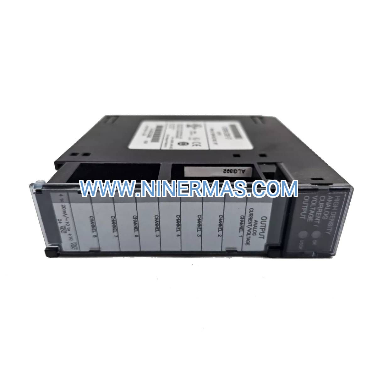
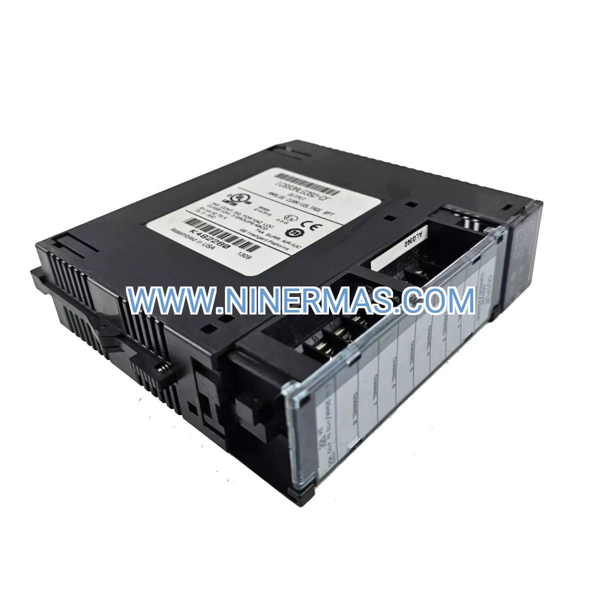
The IC693ALG392 is an 8-channel analog voltage output module engineered for GE Fanuc Series 90-30 programmable logic controller platforms. Through precision 12-bit digital-to-analog conversion and 0-10 VDC output capability, this module enables accurate control of variable frequency drives, proportional valves, servo actuators, and analog instrumentation across industrial automation environments.
Designed for high-reliability applications in process control, manufacturing automation, building management, and water treatment facilities, the IC693ALG392 addresses critical challenges including signal drift, electrical noise interference, system downtime during maintenance, and integration complexity in multi-vendor control architectures. With 500V optical isolation, hot-swappable design, and removable terminal blocks, this module minimizes installation time, reduces troubleshooting effort, and extends mean time between failures.
Ideal for system integrators, control panel builders, OEM equipment manufacturers, and facility maintenance teams requiring proven analog output solutions. Our engineering team provides comprehensive selection guidance, wiring diagrams, and configuration support to ensure optimal system performance. Contact us with your application requirements for customized recommendations and technical consultation.
Core Functions & Technical Advantages
- Multi-Channel Precision Output
Delivers eight independent 0-10 VDC voltage signals with 12-bit resolution (4096 discrete levels), enabling fine-grained control of analog devices. Each channel updates every 10 milliseconds, supporting responsive closed-loop control strategies for dynamic process variables. - Robust Electrical Isolation
500-volt optical isolation between field circuits and backplane logic protects sensitive PLC components from voltage spikes, ground loops, and electromagnetic interference common in industrial power distribution environments, reducing nuisance faults and equipment damage. - Hot-Swap Maintenance Capability
Replace or upgrade modules during live system operation without halting production processes. Keyed connectors and automatic configuration recognition minimize human error during service procedures, cutting maintenance windows from hours to minutes. - Diagnostic Status Indication
Dual-color LED indicators provide real-time feedback on module health, communication status, and output fault conditions. Accelerates troubleshooting by pinpointing issues to specific channels or system-level communication failures without requiring diagnostic software. - Industrial Environmental Resilience
Operates reliably across 0°C to 60°C ambient temperature range with 5-95% non-condensing humidity tolerance. Conformal coating and ruggedized construction withstand vibration, dust, and chemical exposure typical in manufacturing plants, wastewater facilities, and outdoor enclosures. - Simplified Wiring & Installation
Removable screw-terminal blocks allow pre-wiring of field cables before module insertion, reducing panel assembly time. Color-coded terminal labels and standardized pinouts minimize wiring errors and simplify documentation for multi-site deployments.
Typical Application Scenarios
This module serves industries and processes demanding stable, repeatable analog control with minimal calibration drift:
- Chemical & Pharmaceutical Process Control
Regulate reactor temperatures, pressure vessels, and chemical dosing pumps through precise voltage signals to control valves and variable speed drives. Maintains product quality consistency while reducing raw material waste in batch and continuous processes. - Water & Wastewater Treatment Systems
Control clarifier rake speeds, chemical feed pumps, and aeration blower VFDs to optimize treatment efficiency and energy consumption. Integrates with SCADA systems for remote monitoring and automated response to flow rate variations and regulatory compliance reporting. - HVAC & Building Automation
Modulate chilled water valve positions, variable air volume damper actuators, and cooling tower fan speeds to maintain comfort conditions while minimizing energy costs. Supports BACnet and Modbus integration for enterprise building management platforms. - Manufacturing Assembly & Material Handling
Position servo-driven conveyors, regulate pneumatic pressure for pick-and-place systems, and control tension in web processing equipment. Synchronizes with high-speed digital I/O for coordinated motion control in packaging, automotive, and electronics assembly lines. - Food & Beverage Production
Manage mixer speeds, oven temperature profiles, and filling machine flow rates with sanitary-rated actuators. Meets clean-room requirements and supports recipe-driven production with programmable output profiles stored in PLC memory.
Technical Parameters & Selection Guide
| Parameter | Specification |
|---|---|
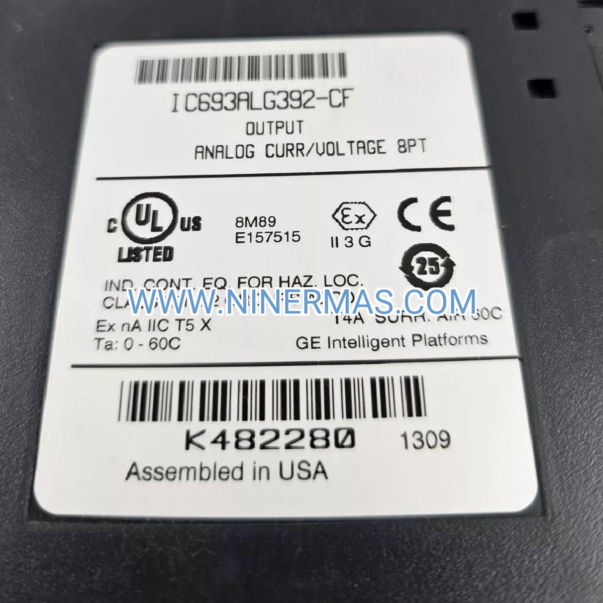
| Catalog Number | IC693ALG392 |
| Output Channels | 8 single-ended voltage outputs |
| Output Voltage Range | 0 to +10 VDC |
| Resolution | 12-bit (2.44 mV per step) |
| Accuracy | ±0.5% full scale @ 25°C |
| Temperature Drift | ±0.02% per °C |
| Update Rate | 10 ms per channel |
| Output Current Capacity | 5 mA maximum per channel |
| Isolation Voltage | 500 VAC field-to-logic |
| Power Consumption | 4.5W typical (backplane powered) |
| Operating Temperature | 0°C to 60°C (32°F to 140°F) |
| Storage Temperature | -40°C to 85°C (-40°F to 185°F) |
| Relative Humidity | 5% to 95% non-condensing |
| Backplane Compatibility | Series 90-30 5-slot, 10-slot expansion racks |
| Mounting Orientation | Horizontal or vertical (DIN rail optional) |
| Agency Approvals | UL Listed, CE marked, CSA certified |
| MTBF | >500,000 hours (MIL-HDBK-217F) |
Selection Considerations: When specifying the IC693ALG392, evaluate total channel count requirements, maximum cable run distances (recommend <300m shielded twisted pair), load impedance of connected devices (minimum 2kΩ recommended), and environmental enclosure ratings. For current output applications (4-20mA), consider the IC693ALG391 companion module. Systems requiring mixed voltage/current outputs benefit from the IC693ALG442 combination module. Consult our application engineers with your I/O list, panel layout, and performance specifications for optimized system architecture recommendations.
System Integration & Expansion Options
Power Supply Requirements: The IC693ALG392 draws operating power exclusively from the Series 90-30 backplane bus. Ensure adequate power budget when configuring racks – typical 5-slot base systems support up to 15W total I/O load with IC693PWR321 power supply. For expanded configurations exceeding 10 modules, specify IC693PWR330 high-capacity supplies or implement distributed power architectures.
Communication & Networking: Integrate with Ethernet/IP, DeviceNet, or Profibus networks using IC693CMM311 or IC693BEM331 communication modules. Supports remote I/O configurations via GE Genius or RX3i distributed I/O for cabinet-to-cabinet distances exceeding 100 meters. SCADA connectivity available through OPC-UA, Modbus TCP, or proprietary SNP protocols.
Complementary I/O Modules: Pair with IC693ALG223 analog input modules for closed-loop PID control, IC693MDL655 digital input modules for limit switch monitoring, and IC693MDL940 relay output modules for on/off device control. Complete system solutions include IC693CHS391 expansion chassis, IC693CBL300 interconnect cables, and IC693ACC300 terminal block kits.
Software & Programming: Configure and program using GE Proficy Machine Edition (v9.0 or later) or legacy Logicmaster 90-30 software. Module appears as standard %AQ (analog output) memory addresses in ladder logic, structured text, or function block programming environments. Supports online editing, forcing, and trending for commissioning and diagnostics.
Delivery, Service & Quality Assurance
Lead Time: Factory-new IC693ALG392 modules ship within 3-5 business days from stock. Custom-configured systems with integrated testing require 10-15 business days. Expedited same-day shipping available for critical downtime situations (subject to inventory availability).
Warranty Coverage: All modules include a comprehensive 12-month warranty against manufacturing defects and component failures. Warranty covers replacement parts, return shipping, and technical support labor. Extended warranty programs available for mission-critical applications requiring 24/7 uptime guarantees.
Technical Support: Our certified GE automation specialists provide complimentary pre-sale application engineering, post-sale configuration assistance, and lifetime troubleshooting support. Services include remote diagnostics via TeamViewer, on-site commissioning (regional availability), and custom training programs for maintenance personnel.
Documentation Package: Each module ships with installation quick-start guide, dimensional drawings, terminal wiring diagrams, and digital access to full user manual (GFK-1503). CAD files (DWG/DXF), EPLAN macros, and sample PLC code available upon request for system integrators.
Quality Verification: Every unit undergoes factory acceptance testing including output linearity verification, isolation voltage testing, and thermal cycling. Modules are shipped in anti-static packaging with serialized quality control certificates traceable to manufacturing batch records.
Frequently Asked Questions
Q: How does the IC693ALG392 integrate with existing Series 90-30 PLC systems?
A: The module installs in any available slot on Series 90-30 5-slot or 10-slot base/expansion racks. After physical installation, configure the module location in Proficy Machine Edition software – the system automatically recognizes the module type and allocates %AQ memory addresses. No DIP switches or manual addressing required. Total configuration time typically under 5 minutes for experienced users.
Q: What is the maximum number of IC693ALG392 modules supported in a single rack?
A: A standard 10-slot expansion rack can accommodate up to 8 I/O modules (slots 1-8, with slot 0 reserved for power supply and slot 9 for CPU or communication module). Practical limits depend on total backplane power budget – with 4.5W per module, you can install 6-7 analog output modules alongside typical CPU and communication modules without exceeding IC693PWR321 capacity. For higher density requirements, implement multiple racks with expansion cables.
Q: Can the IC693ALG392 drive 4-20mA devices, or is it voltage-only?
A: This module provides voltage outputs exclusively (0-10 VDC). For current loop applications requiring 4-20mA signals, specify the IC693ALG391 current output module. Many modern actuators and VFDs accept either voltage or current inputs – verify your field device specifications. If your application requires both signal types, the IC693ALG442 combination module offers 4 voltage + 4 current outputs in a single slot.
Q: What cable specifications are recommended for output wiring to minimize signal degradation?
A: Use 18-22 AWG shielded twisted-pair cable with drain wire grounded at the module end only (avoid ground loops). For runs under 100 meters, standard instrumentation cable (Belden 8760 or equivalent) provides adequate performance. Runs exceeding 100 meters or high-EMI environments require low-capacitance cable (<100 pF/m) with 100% foil shield coverage. Maintain minimum 150mm separation from AC power cables and VFD output conductors.
Q: Does the module require external power supplies, or is backplane power sufficient?
A: The IC693ALG392 operates entirely from Series 90-30 backplane power – no external supplies needed. The module draws 4.5W from the +5VDC backplane bus, which is provided by rack-mounted power supplies (IC693PWR321, IC693PWR330, etc.). Ensure your power supply selection accounts for total I/O load plus 20% safety margin for reliable operation.
Q: How do I troubleshoot an output channel that appears non-functional or inaccurate?
A: First, verify the module status LED shows green (normal operation). Use Proficy Machine Edition to force the suspect channel to 50% output and measure voltage at the terminal block – should read 5.0 VDC ±0.05V. If voltage is absent, check terminal block seating and backplane connection. If voltage is present but field device doesn't respond, verify device input impedance exceeds 2kΩ and cable continuity. Persistent issues may indicate field device failure or cable damage rather than module fault.
Request Technical Consultation & Quotation
To receive customized system recommendations, detailed pricing, and application-specific configuration guidance, please provide the following project information:
- Project name and industry sector
- Total analog output channel count required
- Output signal types needed (voltage/current/mixed)
- Controlled device types (VFDs, valves, actuators, etc.)
- Maximum cable run distances
- Environmental conditions (temperature range, enclosure type)
- Existing PLC platform (CPU model, rack configuration)
- Timeline and budget constraints
Our application engineering team will respond within 24 hours with tailored solutions, bill of materials, and implementation roadmap. For urgent requirements, call our technical hotline for immediate assistance.
© 2026 NINERMAS COMPANY LIMITED. All rights reserved.
Original Source: https://ninermas.com
Contact: sale@ninermas.com | +0086 187 5021 5667


Contact Info
-
Address:22 / F, South Wo Hang building, 148 Wing Lok Street, Sheung Wan, Western District, Hong Kong
-
Phone:+8618750215667
-
Email: