GE F650 Digital Bay Controller | Feeder Protection & Substation Automation Relay
Description
GE F650 Digital Bay Controller – Industrial-Grade Feeder Protection & Substation Automation System
The GE F650 Digital Bay Controller is an advanced protection and control device engineered for medium-voltage feeder applications in substations, industrial power distribution networks, and utility infrastructure. Leveraging multi-function protection algorithms, integrated control logic, and IEC 61850 communication protocols, the F650 delivers real-time monitoring, fault detection, and automated switching to ensure power system reliability and operational safety.
Designed for utilities, industrial facilities, renewable energy plants, and critical infrastructure operators, this relay addresses challenges such as overcurrent faults, earth faults, voltage anomalies, breaker failure, and communication bottlenecks. It replaces legacy electromechanical relays with a unified digital platform that reduces panel space, simplifies wiring, and enhances diagnostic capabilities.
Through standardized design and flexible configuration options, the F650 offers seamless integration with SCADA systems, substation automation platforms, and distributed energy resources (DERs). Contact our protection engineers for application-specific configuration, settings files, and technical support tailored to your project requirements.
Core Functions & Advantages
- Comprehensive Feeder Protection
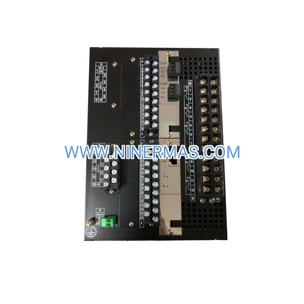
Equipped with overcurrent (50/51), earth fault (50N/51N), directional overcurrent (67/67N), voltage protection (27/59), and breaker failure (50BF) elements. Provides multi-stage coordination to isolate faults rapidly while maintaining selectivity with upstream and downstream devices. - IEC 61850 Native Communication
Supports GOOSE messaging for peer-to-peer interlocking, MMS for SCADA integration, and sampled values (SV) for process bus architectures. Reduces copper wiring, accelerates commissioning, and enables advanced automation schemes such as auto-reclosing and load shedding. - Integrated Control & Monitoring
Built-in programmable logic (similar to PLC functionality) allows custom control sequences, breaker health monitoring, and event-driven actions. Real-time metering of voltage, current, power, energy, and power quality parameters supports operational decision-making and regulatory compliance. - Advanced Fault Recording & Diagnostics
High-resolution oscillography captures waveforms during disturbances, enabling root-cause analysis and system optimization. Time-stamped event logs and sequence-of-events (SOE) records facilitate post-fault investigations and compliance audits. - Robust Protection Against Harsh Environments
Designed to withstand electromagnetic interference (EMI), voltage transients, temperature extremes (-40°C to +70°C), and vibration per IEC 60255 standards. Suitable for outdoor substations, industrial plants, and mobile power systems. - User-Friendly Interface & Configuration Tools
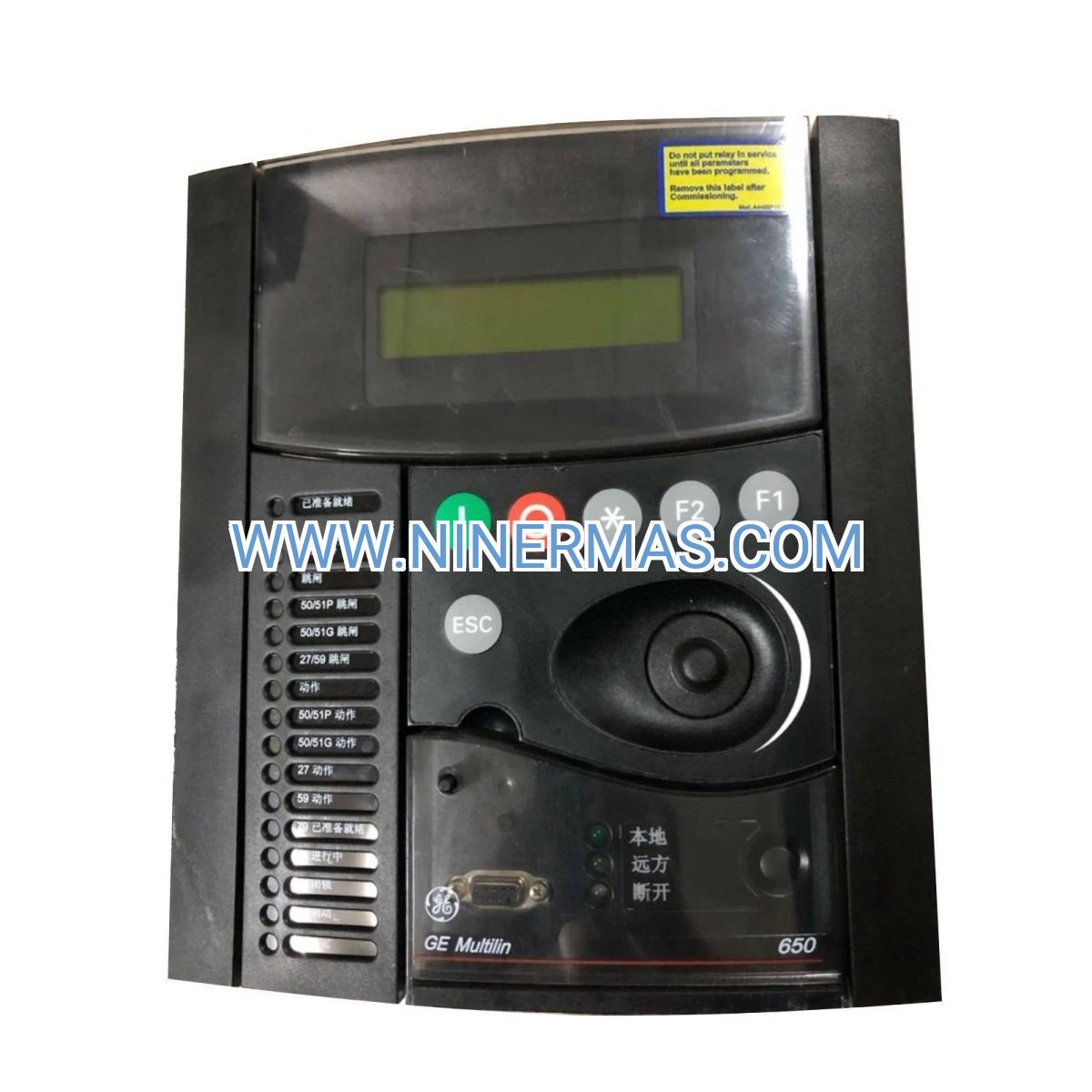
Front-panel HMI with multi-language support displays real-time status, alarms, and measured values. GE's EnerVista software suite enables offline settings preparation, online monitoring, and firmware updates via Ethernet or serial connections.
Typical Application Scenarios
The GE F650 is engineered for applications demanding high reliability, fast fault clearance, and seamless integration with modern substation automation architectures, including:
- Utility Distribution Feeders
Protects medium-voltage feeders (6.6 kV to 35 kV) in urban and rural distribution networks. Coordinates with reclosers, sectionalizers, and upstream transformers to minimize outage duration and improve service continuity for residential and commercial customers. - Industrial Power Distribution Systems
Safeguards critical loads in manufacturing plants, petrochemical facilities, mining operations, and data centers. Integrates with motor protection relays, generator controllers, and energy management systems to optimize uptime and reduce production losses. - Renewable Energy & DER Integration
Manages protection and control for solar farms, wind parks, and battery energy storage systems (BESS). Supports anti-islanding, reverse power detection, and grid code compliance (IEEE 1547, VDE-AR-N 4120) to ensure safe interconnection with utility grids. - Substation Automation & Smart Grid Projects
Serves as a bay-level intelligent electronic device (IED) in IEC 61850-based substations. Participates in distributed automation schemes such as adaptive protection, wide-area monitoring, and demand response programs.
Technical Parameters & Selection Guide
To facilitate engineering design and procurement, we provide key specifications for the GE F650 series. Custom configurations are available to match project-specific voltage levels, CT/VT ratios, communication protocols, and environmental conditions.
| Parameter | Specification |
|---|---|
| Rated Voltage (AC) | 110 V / 220 V / 240 V (configurable) |
| Rated Current (CT Input) | 1 A / 5 A nominal, up to 100× for 1 second |
| Protection Functions | 50/51, 50N/51N, 67/67N, 27/59, 81O/U, 50BF, 79, 25, 46, and more |
| Communication Protocols | IEC 61850 (GOOSE, MMS, SV), Modbus RTU/TCP, DNP3, IEC 60870-5-103 |
| Digital Inputs / Outputs | Up to 32 DI / 24 DO (model-dependent) |
| Operating Temperature | -40°C to +70°C |
| Enclosure Rating | IP54 (front), IP20 (rear) or IP65 (optional) |
| Compliance Standards | IEC 60255, IEEE C37.90, UL, CE |
| Mounting | Panel flush mount or 19-inch rack (4U height) |
Selection Recommendations: When specifying the F650, consider system voltage, CT/VT ratios, required protection functions, communication architecture (hardwired vs. IEC 61850), and environmental conditions. For complex applications involving multi-feeder coordination, arc flash mitigation, or integration with legacy SCADA, consult our protection engineers. Provide one-line diagrams, CT/VT specifications, and project timelines for tailored recommendations and quotations.
Extended Capabilities
- Cybersecurity Features: Role-based access control (RBAC), encrypted communication (TLS), and audit trails comply with NERC CIP and IEC 62351 standards, protecting critical infrastructure from cyber threats.
- Adaptive Protection Schemes: Dynamic settings adjustment based on system topology, load conditions, or DER penetration levels enhances protection sensitivity and reduces nuisance tripping.
- Synchrophasor Measurement (Optional): IEEE C37.118 phasor measurement unit (PMU) functionality enables wide-area situational awareness and post-disturbance analysis for transmission and large distribution systems.
- Redundancy & Hot-Swap: Dual power supply inputs and redundant communication ports ensure continuous operation during maintenance or component failures.
Delivery, Service & Quality Assurance
Lead Time: Standard configurations typically ship within 4–6 weeks; custom-engineered solutions require 8–12 weeks depending on complexity and factory workload.
Warranty: Backed by a minimum 2-year manufacturer warranty covering defects in materials and workmanship. Extended warranty and service contracts available for mission-critical installations.
Technical Support: Comprehensive support includes pre-sales application engineering, settings calculation, commissioning assistance (remote or on-site, region-dependent), and post-installation troubleshooting. Factory acceptance testing (FAT) and witness testing can be arranged upon request.
Documentation Package: Each unit ships with detailed instruction manuals, electrical schematics, terminal wiring diagrams, settings templates, and IEC 61850 ICD/CID files to streamline installation, commissioning, and long-term maintenance.
Certifications: Manufactured in ISO 9001-certified facilities with full traceability. Products meet international standards (IEC, IEEE, UL, CE) and can be supplied with third-party test reports and material certificates for regulatory compliance.
Frequently Asked Questions (FAQ)
Q: How does the GE F650 Digital Bay Controller integrate with existing substation SCADA systems?
A: The F650 supports multiple protocols including IEC 61850 MMS, Modbus TCP/RTU, DNP3, and IEC 60870-5-103. For legacy systems, serial or Ethernet gateways can bridge communication. IEC 61850 configurations use standardized ICD files for plug-and-play integration with modern substation automation platforms.
Q: What is the maximum number of protection functions the F650 can execute simultaneously?
A: The F650 is a multi-function relay capable of running 20+ protection elements concurrently, including overcurrent, earth fault, directional, voltage, frequency, breaker failure, and custom logic. Actual function availability depends on the ordered model and firmware version.
Q: Can the F650 be used for generator or transformer protection applications?
A: While the F650 is optimized for feeder protection, it can be applied to small generators or distribution transformers when protection requirements align with its function set. For dedicated generator or transformer protection, consider GE's G60 or T60 series relays, which offer specialized algorithms such as differential, loss-of-field, and restricted earth fault.
Q: What are the environmental and installation requirements for the F650?
A: The relay operates reliably in ambient temperatures from -40°C to +70°C and withstands humidity, vibration, and EMI per IEC 60255. Standard enclosures are IP54 (front) / IP20 (rear); IP65-rated versions are available for harsh outdoor or dusty environments. Panel cutout dimensions and mounting hardware are detailed in the installation manual.
Q: Does the F650 support remote firmware updates and cybersecurity compliance?
A: Yes. Firmware can be updated remotely via Ethernet using GE's EnerVista software, with version control and rollback capabilities. The relay includes cybersecurity features such as password protection, role-based access, encrypted communication (TLS), and event logging to meet NERC CIP and IEC 62351 requirements.
Q: How do I obtain settings files, one-line diagrams, or application notes for my specific project?
A: Contact our protection engineering team with your project details: system voltage, CT/VT ratios, fault levels, coordination requirements, and communication architecture. We will provide customized settings files, coordination curves, and application guidance. For complex projects, on-site commissioning support and training can be arranged.
Request a Quote or Technical Consultation
To receive a detailed selection proposal, pricing, or technical support, please provide the following information: project name and location, application type (utility feeder, industrial distribution, renewable integration), system voltage and fault level, CT/VT specifications, required communication protocols, environmental conditions, and desired delivery timeline. Our protection engineers will respond with a tailored solution, including model recommendations, settings templates, and lead-time estimates.
© 2026 NINERMAS COMPANY LIMITED. All rights reserved. Original Source: https://ninermas.com Contact: sale@ninermas.com | +0086 187 5021 5667


Contact Info
-
Address:22 / F, South Wo Hang building, 148 Wing Lok Street, Sheung Wan, Western District, Hong Kong
-
Phone:+8618750215667
-
Email: