GE F650 Digital Bay Controller | Advanced Feeder Protection Relay for Substation Automation
Description
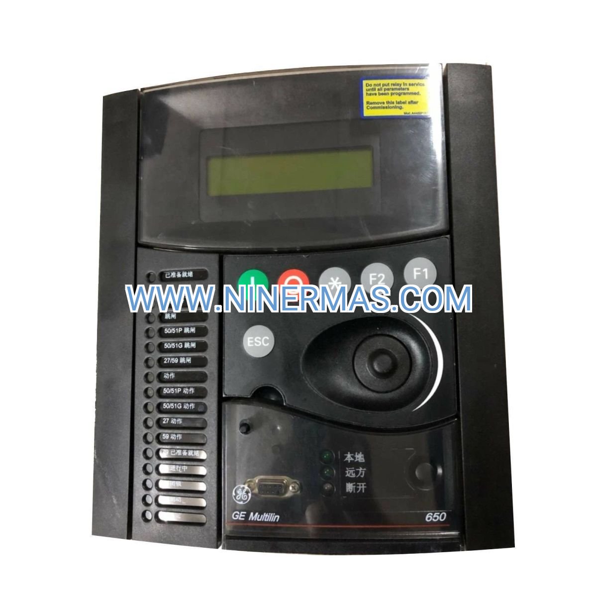
GE F650 Digital Bay Controller (Industrial-Grade Feeder Protection System)
The GE F650MAEF2G0HI Digital Bay Controller is an advanced protection and control device designed for medium-voltage feeder circuits in substations, industrial plants, and utility distribution networks. Leveraging multi-function protection algorithms, IEC 61850 communication, and flexible I/O architecture, it delivers reliable overcurrent, earth fault, directional, and voltage protection—while enabling seamless integration into modern SCADA and substation automation systems.
Ideal for utility substations, industrial power distribution, renewable energy plants, and critical infrastructure projects, the F650 addresses challenges such as complex fault detection, communication protocol compatibility, limited bay-level visibility, and the need for scalable protection schemes. It is particularly suited for applications requiring high reliability, real-time monitoring, and compliance with international standards.
Through standardized configuration tools and customizable protection settings, this controller offers comprehensive fault protection, advanced communication capabilities, modular design flexibility, and reduced commissioning time—making it the preferred choice for consulting engineers, system integrators, utility operators, and OEM partners. Contact our application engineers for tailored protection schemes, configuration files, and technical quotations.
Core Functions & Advantages
- Multi-Function Protection Suite
Integrates overcurrent (ANSI 50/51), earth fault (50N/51N), directional (67/67N), under/overvoltage (27/59), and frequency protection (81) in a single device, reducing panel space and wiring complexity while improving system coordination. - IEC 61850 Native Communication
Supports GOOSE messaging and MMS client/server for horizontal peer-to-peer interlocking and vertical SCADA integration, enabling faster fault isolation, reduced copper wiring, and future-proof substation digitalization. - Flexible I/O & Expansion Modules
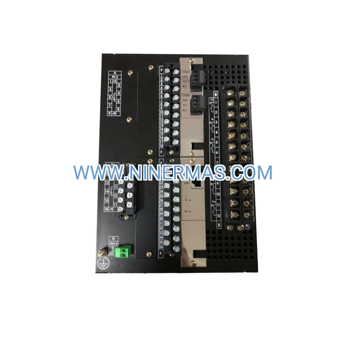
Configurable digital inputs, relay outputs, and analog measurement channels accommodate diverse CT/VT configurations, RTD monitoring, and auxiliary control requirements—adaptable to greenfield and retrofit projects alike. - Comprehensive Event & Fault Recording
High-resolution oscillography, sequence-of-events (SOE) recording with 1 ms resolution, and disturbance fault analysis facilitate rapid root-cause diagnosis, regulatory compliance, and continuous system optimization. - Intuitive Configuration & Diagnostics
GE's EnerVista software suite provides graphical logic editing, one-line diagram visualization, and remote parameter adjustment, significantly reducing engineering time and on-site commissioning effort. - Robust Design for Harsh Environments
Wide operating temperature range (-40°C to +70°C), high EMC immunity (IEC 61000-4 series), and conformal-coated PCBs ensure reliable operation in extreme climates, high-pollution areas, and electrically noisy industrial settings.
Typical Application Scenarios
The F650 controller is engineered for demanding protection and control tasks across multiple sectors:
- Utility Distribution Substations
Protects medium-voltage feeders (6 kV to 35 kV) in primary and secondary substations, coordinating with upstream relays and downstream reclosers to minimize outage duration and improve grid reliability. - Industrial Power Distribution & On-Site Generation
Safeguards critical motor feeders, transformer feeders, and generator tie circuits in manufacturing plants, petrochemical facilities, and data centers—ensuring process continuity and equipment longevity. - Renewable Energy & Microgrid Projects
Manages protection and synchronization for solar inverter feeders, wind turbine collector systems, and battery energy storage interconnections, supporting grid-code compliance and islanding detection. - Infrastructure & Transportation Systems
Deployed in railway traction substations, airport ground power systems, and metro networks where high availability, fast fault clearing, and remote monitoring are mission-critical. - Retrofit & Modernization Programs
Replaces legacy electromechanical or early-generation digital relays with minimal panel modifications, leveraging existing CT/VT infrastructure while unlocking advanced communication and diagnostics.
Technical Parameters & Selection Guide
To streamline engineering and procurement, we provide key electrical, communication, and environmental specifications. Custom configurations are available to match project-specific requirements.
| Parameter | Specification |
|---|---|
| Rated Voltage (AC) | Phase: 100–240 V AC; Auxiliary: 24–250 V DC / 100–240 V AC |
| Rated Current (CT Primary) | 1 A or 5 A nominal, programmable ratio up to 50,000:1 |
| Protection Functions | 50/51, 50N/51N, 67/67N, 27/59, 81O/U, 79, 25, 46, 49, 50BF, and more |
| Communication Protocols | IEC 61850 (Ed. 1/2), Modbus RTU/TCP, DNP3, IEC 60870-5-103 |
| Digital Inputs / Outputs | Up to 32 DI / 24 DO (configurable via expansion modules) |
| Analog Inputs | 4–8 RTD/mA inputs for temperature and auxiliary monitoring |
| Operating Temperature | -40°C to +70°C (storage: -40°C to +85°C) |
| Enclosure Rating | IP20 (front), IP40 (rear); optional IP54 for harsh environments |
| Compliance Standards | IEC 60255, IEEE C37.90, IEC 61850, UL/CSA, CE |
| Dimensions (H×W×D) | Approx. 177 mm × 180 mm × 230 mm (1/2 rack 19" mountable) |
Selection Recommendations: When specifying the F650, consider CT/VT ratios, required protection functions, communication protocol preferences, number of I/O points, auxiliary power supply availability, and panel space constraints. For complex applications—such as bus-tie protection, transformer differential, or generator synchronization—consult our protection engineers to validate settings and coordination studies. Provide single-line diagrams, fault levels, and existing relay schedules for optimized configuration proposals.
Extended Capabilities
- Programmable Logic (FlexLogic™): Create custom interlocking, auto-transfer, and load-shedding schemes using graphical logic gates—no external PLC required.
- Cybersecurity Features: Role-based access control (RBAC), encrypted communication (TLS), and audit logging comply with NERC CIP and IEC 62351 standards.
- Synchrophasor Measurement (Optional): IEEE C37.118 PMU functionality for wide-area monitoring and real-time grid stability analysis.
- Multi-Language HMI: Front-panel display supports English, Chinese, Spanish, and other languages for global deployment and local operator training.
Delivery, Service & Quality Assurance
Lead Time: Standard catalog models ship within 4–6 weeks; custom-configured units (specific I/O, communication cards, or firmware) require 6–10 weeks. Expedited delivery available upon request.
Warranty: 3-year manufacturer warranty covering materials and workmanship; extended service agreements and spare-parts kits available.
Commissioning Support: Remote configuration assistance, on-site startup services (region-dependent), and relay setting validation included. Post-commissioning health checks and firmware updates offered under service contracts.
Technical Documentation: Each unit ships with instruction manual, protection setting templates, IEC 61850 ICD/CID files, CAD drawings (DXF/DWG), and wiring diagrams—facilitating seamless integration and long-term maintenance.
Certifications: Factory acceptance testing (FAT) reports, type-test certificates (IEC 60255-27, IEEE C37.90.1), and calibration certificates traceable to national standards provided upon request.
Frequently Asked Questions (FAQ)
Q: How does the GE F650 Digital Bay Controller integrate with existing substation SCADA systems?
A: The F650 supports multiple protocols—IEC 61850 (GOOSE/MMS), Modbus, DNP3, and IEC 60870-5-103—allowing seamless connection to legacy RTUs or modern IEC 61850 station buses. Configuration is performed via EnerVista software, and ICD files can be imported into substation configuration tools (e.g., SAS, PCM600) for automated signal mapping.
Q: Can the F650 be used for transformer or motor protection, or is it limited to feeder applications?
A: While optimized for feeder protection, the F650's flexible function set supports transformer overcurrent/earth fault backup, motor thermal overload (49), and underfrequency load shedding (81). For dedicated transformer differential (87T) or motor management, consider GE's T60 or M60 series relays.
Q: What is the typical energy savings or operational benefit of upgrading to the F650 from electromechanical relays?
A: Direct energy savings are minimal (the relay itself consumes <15 W), but operational benefits include faster fault clearing (reducing equipment stress and arc-flash energy), reduced panel wiring (lowering installation labor by 20–30%), and predictive maintenance via continuous self-diagnostics—collectively extending asset life and minimizing unplanned downtime.
Q: What are the environmental and installation requirements for the F650 controller?
A: The standard IP20 front / IP40 rear enclosure suits indoor switchgear and control rooms with ambient temperatures from -40°C to +70°C. For outdoor kiosks or high-humidity environments, specify IP54-rated models and ensure adequate ventilation. Panel cutout dimensions and mounting rail specifications are detailed in the installation manual.
Q: Does the F650 support remote monitoring, firmware updates, and cybersecurity compliance?
A: Yes. The F650 offers Ethernet-based remote access (with password protection and RBAC), supports secure protocols (SSH, TLS), and logs all configuration changes for audit trails. Firmware can be updated remotely via EnerVista software, and the device meets NERC CIP and IEC 62351 guidelines when deployed with proper network segmentation and firewall policies.
Q: How many feeders can one F650 unit protect, and can it be expanded later?
A: Each F650 unit protects a single feeder bay (one set of CT/VT inputs). For multi-feeder applications, deploy multiple F650 units and coordinate settings via IEC 61850 GOOSE for interlocking. I/O expansion modules can be added post-installation to accommodate additional auxiliary contacts or RTD sensors without replacing the main unit.
Request a Customized Solution
To receive a detailed protection scheme, configuration file, technical proposal, or quotation, please provide the following project information: project name and location, application type (utility/industrial/renewable), system voltage and fault level, CT/VT ratios, number of feeders or bays, required communication protocols, existing SCADA platform, and any special environmental or regulatory requirements. Our protection engineers will deliver a tailored recommendation with single-line diagrams, relay settings, and commercial terms within 48–72 hours.
© 2026 NINERMAS COMPANY LIMITED. All rights reserved. Original Source: https://ninermas.com Contact: sale@ninermas.com | +0086 187 5021 5667


Contact Info
-
Address:22 / F, South Wo Hang building, 148 Wing Lok Street, Sheung Wan, Western District, Hong Kong
-
Phone:+8618750215667
-
Email: