GE F650 Digital Bay Controller | Feeder Protection Relay for Substation Automation | IEC 61850
Description
GE F650 Digital Bay Controller (Industrial-Grade Feeder Protection & Automation System)
The GE F650CABF1G0HI10NBNA Digital Bay Controller is an advanced protection and control device engineered for medium-voltage feeder circuits, transformer bays, and motor protection applications in electrical substations. Leveraging multi-function relay technology with integrated IEC 61850 communication, it delivers real-time monitoring, fault detection, and automated switching control to enhance grid reliability and operational efficiency.
Designed for utilities, industrial plants, renewable energy facilities, and infrastructure projects, the F650 addresses critical challenges including delayed fault response, communication protocol incompatibility, limited diagnostic visibility, and manual switchgear operation risks. Its modular architecture supports seamless integration with SCADA systems, enabling centralized control and predictive maintenance strategies.
Through standardized design and flexible configuration options, this controller offers superior protection accuracy, IEC 61850 GOOSE/MMS protocol support, comprehensive event recording, and intuitive HMI interface. Ideal for consulting engineers, EPC contractors, system integrators, and facility operators seeking reliable substation automation solutions. Contact our application engineers for customized protection schemes and technical specifications.
Core Functions & Advantages
- Multi-Function Protection Suite
Integrates overcurrent (50/51), directional (67), earth fault (50N/51N), voltage (27/59), frequency (81), and breaker failure (50BF) protection elements in a single device, reducing panel space and wiring complexity while improving coordination accuracy. - IEC 61850 Native Communication
Supports GOOSE messaging for peer-to-peer interlocking and MMS for client-server data exchange, enabling seamless integration with modern substation automation architectures and reducing commissioning time by up to 40% compared to legacy protocols. - Advanced Fault Recording & Diagnostics
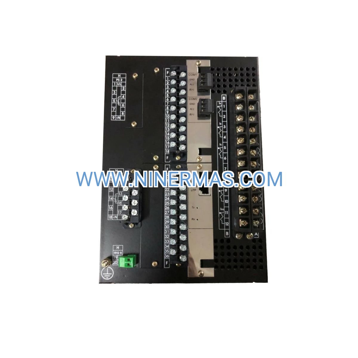
Captures high-resolution waveform data (up to 64 samples/cycle), sequence-of-events with 1ms resolution, and disturbance records for post-fault analysis, accelerating root cause identification and minimizing downtime. - Flexible I/O Configuration
Offers configurable digital inputs (up to 32), output contacts (up to 24), and analog inputs (voltage/current) to accommodate diverse bay configurations, from simple feeders to complex bus-tie schemes, without hardware modifications. - Cybersecurity & Redundancy
Implements role-based access control, encrypted communication (TLS), and dual Ethernet ports for network redundancy, meeting IEC 62351 security standards and ensuring continuous operation during network disturbances. - User-Friendly Interface & Remote Access
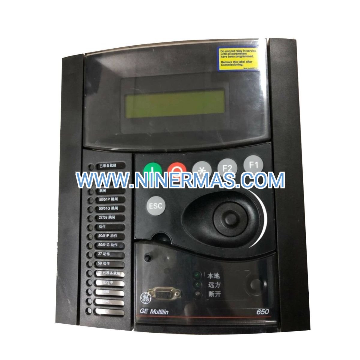
Features a backlit LCD display with multi-language support (English/Chinese/Spanish), front-panel keypad for local operation, and web-based HMI for remote monitoring via standard browsers, reducing training requirements and enabling 24/7 system oversight.
Typical Application Scenarios
The GE F650 Digital Bay Controller is engineered for mission-critical power distribution environments demanding high reliability, fast fault clearance, and comprehensive system visibility, including:
- Utility Distribution Substations
Protects medium-voltage feeders (6.6kV–36kV) in primary and secondary substations, coordinating with upstream transmission protection and downstream distribution automation devices to maintain service continuity during faults. - Industrial Power Systems
Safeguards critical loads in manufacturing plants, petrochemical facilities, mining operations, and data centers, where unplanned outages result in significant production losses or safety hazards, supporting both radial and ring-main configurations. - Renewable Energy Integration
Manages feeder protection and synchronization control for solar farms, wind parks, and battery energy storage systems connecting to utility grids, ensuring compliance with grid codes (IEEE 1547, VDE-AR-N 4120) and anti-islanding requirements. - Infrastructure & Transportation
Deployed in railway traction substations, airport ground power systems, and metro transit networks to protect auxiliary power supplies, ensuring uninterrupted operation of essential services and passenger safety systems. - Substation Retrofit & Modernization
Replaces obsolete electromechanical or early-generation digital relays in aging substations, providing backward compatibility with existing CTs/VTs while enabling migration to IEC 61850-based automation without complete system overhaul.
Technical Parameters & Selection Guide
To facilitate engineering design and procurement, we provide standardized configuration options based on common application requirements. Custom configurations are available to match specific project specifications.
| Parameter | Specification |
|---|---|
| Model Code | F650CABF1G0HI10NBNA |
| Rated Voltage (AC) | 85–265V AC/DC (universal power supply) |
| Current Inputs | 5A or 1A nominal, 0.01A–40A measurement range |
| Voltage Inputs | Phase-neutral: 120V, Phase-phase: 208V (configurable) |
| Digital Inputs | Up to 32 channels (24–250V DC/AC) |
| Output Contacts | Up to 24 Form-A (NO), 10A @ 250V AC resistive |
| Communication Ports | Dual Ethernet (IEC 61850), RS485 (Modbus RTU), rear USB |
| Protection Functions | ANSI 50/51, 50N/51N, 67, 27/59, 81, 50BF, 79, 25 |
| Operating Temperature | -40°C to +70°C (-40°F to +158°F) |
| Enclosure Rating | IP54 (front), IP20 (rear) per IEC 60529 |
| Mounting | Panel flush mount or 19" rack (4U height) |
| Compliance Standards | IEC 61850, IEC 60255, IEEE C37.90, UL/CSA certified |
Selection Recommendations:
When specifying the F650 controller, consider the following project parameters: primary system voltage level, CT/VT ratios, required protection functions per single-line diagram, communication protocol requirements (IEC 61850 edition 1/2, DNP3, Modbus), available panel space, and environmental conditions (temperature, humidity, altitude). For complex applications involving bus protection, transformer differential, or generator protection, consult our protection coordination engineers to determine optimal relay configuration and settings. Provide one-line diagrams, fault study reports, and existing relay schedules for accurate proposal preparation.
Extended Capabilities
- Synchrophasor Measurement (PMU) – Optional module for real-time phasor data streaming per IEEE C37.118, supporting wide-area monitoring and stability analysis.
- Arc Flash Detection Integration – Compatible with optical/pressure sensors for ultra-fast arc fault tripping (<2ms), minimizing equipment damage and personnel hazards.
- Condition Monitoring – Tracks breaker operation counters, contact wear indicators, and SF6 gas pressure (via analog inputs) to enable predictive maintenance scheduling.
- Load Shedding & Restoration – Programmable logic for automatic load management during under-frequency or overload conditions, maintaining system stability.
- Cybersecurity Hardening – Supports RBAC (role-based access control), syslog event forwarding, and firmware signature verification to meet NERC CIP compliance requirements.
Delivery, Service & Quality Assurance
Lead Time: Standard configurations ship within 4–6 weeks; custom-engineered solutions require 8–12 weeks depending on I/O complexity and factory testing requirements.
Warranty: 12-month manufacturer warranty covering defects in materials and workmanship; extended warranty and spare parts programs available.
Technical Support: Comprehensive commissioning assistance including protection settings calculation, IEC 61850 SCL file generation, and on-site startup supervision (subject to regional availability). Remote troubleshooting and firmware upgrade support provided throughout product lifecycle.
Documentation Package: Each unit ships with complete electrical schematics, terminal block wiring diagrams, protection function manuals, IEC 61850 ICD files, and Modbus register maps in PDF and editable formats, facilitating integration and maintenance.
Certifications: Factory acceptance testing (FAT) reports, calibration certificates traceable to national standards, and compliance declarations (CE, UL, IEC) included with shipment.
Frequently Asked Questions (FAQ)
Q: How does the GE F650 Digital Bay Controller integrate with existing SCADA systems?
A: The F650 supports multiple communication protocols including IEC 61850 (MMS/GOOSE), DNP3 over TCP/IP or serial, and Modbus RTU/TCP. For legacy SCADA systems, DNP3 or Modbus provides seamless integration; for modern substation automation, IEC 61850 enables plug-and-play connectivity using standardized SCL configuration files. Our engineers can provide pre-configured ICD files and protocol mapping documentation to accelerate commissioning.
Q: What is the maximum number of feeders one F650 controller can protect?
A: A single F650 unit is designed to protect one bay (one circuit breaker with associated feeders or transformers). For multi-feeder applications, multiple F650 units are deployed with peer-to-peer GOOSE messaging for interlocking and bus protection coordination. Each unit operates independently, enhancing system reliability through distributed architecture.
Q: Can the F650 achieve energy savings, and what conditions are required?
A: While the F650 itself is a protection relay (not a variable frequency drive), it contributes to energy efficiency by enabling optimal system operation through load monitoring, power factor correction signaling, and automated capacitor bank switching control. When integrated with energy management systems, it provides real-time power quality data (THD, voltage unbalance) to identify inefficiencies. Typical applications see 5–15% reduction in demand charges through improved power factor and load balancing.
Q: What are the environmental requirements for installation? What is the IP rating?
A: The F650 operates reliably in ambient temperatures from -40°C to +70°C without derating, suitable for outdoor kiosks and harsh industrial environments. The front panel is IP54-rated (dust-protected, splash-resistant), while the rear terminals are IP20 (finger-safe). For higher ingress protection, mount the relay in a NEMA 4X or IP65-rated enclosure. Ensure adequate ventilation to prevent internal condensation in high-humidity climates.
Q: Does the F650 support remote monitoring and data acquisition? Which protocols are compatible?
A: Yes, the F650 features dual Ethernet ports for redundant network connectivity, enabling remote access via web browser (HTTPS), IEC 61850 MMS clients, or DNP3 masters. It supports standard IT protocols including SNTP for time synchronization, SMTP for email alarms, and FTP for disturbance record retrieval. For cybersecurity, configure VPN tunneling or deploy within a secure substation network per IEC 62351 guidelines. Real-time data refresh rates are configurable from 100ms to 10 seconds depending on communication load.
Q: Is factory testing and commissioning support available for the GE F650?
A: Absolutely. All units undergo rigorous factory acceptance testing (FAT) including protection function verification, communication protocol testing, and environmental stress screening. We provide witnessed FAT at our facility or third-party labs upon request. On-site commissioning services include CT/VT polarity checks, protection settings validation using secondary injection test sets, IEC 61850 GOOSE simulation, and operator training. Post-commissioning, we offer 24/7 technical hotline support and remote diagnostics via secure VPN connections.
Request Technical Consultation
To receive a detailed application engineering proposal, quotation, or technical support for the GE F650 Digital Bay Controller, please provide the following project information: project name and location, application type (feeder/transformer/motor protection), system voltage and fault levels, CT/PT ratios, required protection functions per ANSI/IEC codes, communication protocol preferences, quantity required, and delivery timeline. Our protection engineers will respond within 24 hours with customized relay settings, single-line diagram markups, and budget pricing.
© 2026 NINERMAS COMPANY LIMITED. All rights reserved. Original Source: https://ninermas.com
Contact: sale@ninermas.com | +0086 187 5021 5667


Contact Info
-
Address:22 / F, South Wo Hang building, 148 Wing Lok Street, Sheung Wan, Western District, Hong Kong
-
Phone:+8618750215667
-
Email: