GE F650 Digital Bay Controller | Feeder Protection Relay for Substation Automation | IEC 61850
Description
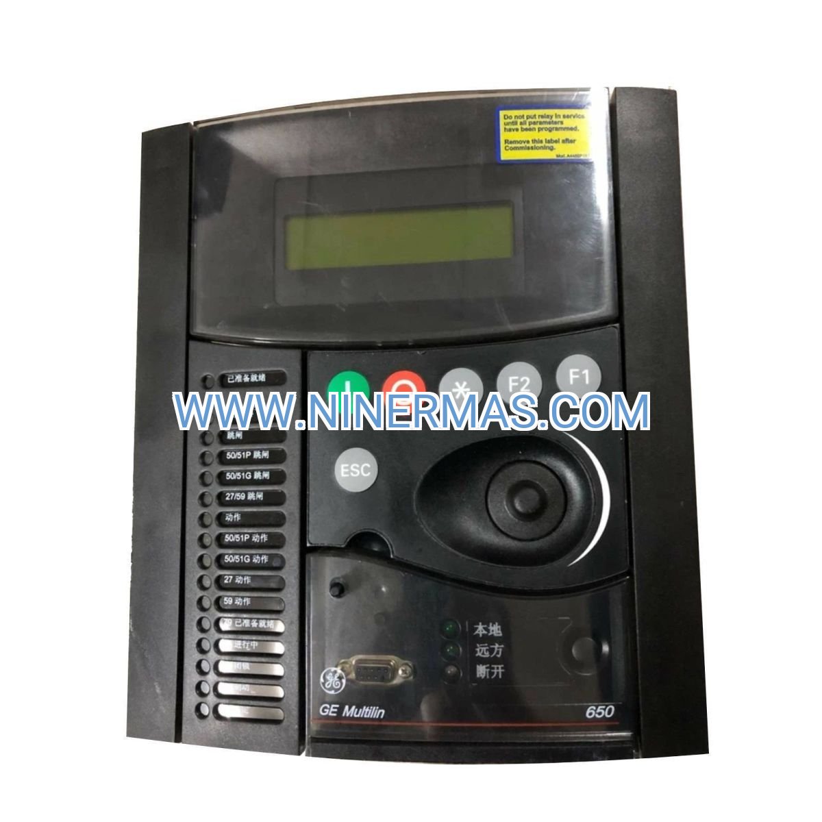
GE F650 Digital Bay Controller (Industrial-Grade Feeder Protection System)
The GE F650 Digital Bay Controller is an advanced feeder protection and control device designed for medium-voltage switchgear, substations, and industrial power distribution systems. Through integrated microprocessor-based protection algorithms, IEC 61850 communication protocol, and comprehensive monitoring capabilities, it delivers reliable overcurrent protection, fault detection, and real-time system diagnostics.
Ideal for utility substations, industrial plants, renewable energy facilities, and commercial buildings, the F650 addresses critical challenges including protection coordination complexity, communication interoperability, limited fault visibility, and maintenance inefficiencies. It provides precise fault location, event recording, and seamless integration with SCADA systems.
Engineered with standardized design and flexible configuration options, this relay offers superior protection accuracy, multi-protocol communication support, intuitive HMI interface, and robust construction for harsh environments. It serves protection engineers, system integrators, utility operators, and facility managers seeking reliable, future-proof feeder protection solutions. Contact our application engineers for customized protection schemes and technical consultation.
Core Functions & Advantages
- Comprehensive Feeder Protection
Provides overcurrent (ANSI 50/51), earth fault (50N/51N), directional (67/67N), and thermal overload (49) protection with high-speed fault clearing to minimize equipment damage and system downtime. - Advanced Bay Control & Automation
Integrates circuit breaker control, interlocking logic, auto-reclosing (79), and synchronism check (25) functions, reducing panel space and wiring complexity compared to discrete relay systems. - IEC 61850 Native Communication
Supports GOOSE messaging and MMS services for seamless substation automation integration, enabling faster commissioning and reduced copper wiring by up to 40% versus conventional hardwired schemes. - Comprehensive Monitoring & Diagnostics
Real-time metering of voltage, current, power, energy, and power quality parameters with disturbance recording and sequence-of-events logging for rapid fault analysis and predictive maintenance. - Flexible Configuration & Scalability
Programmable logic, customizable protection settings, and modular I/O expansion accommodate diverse application requirements from simple feeders to complex distribution schemes. - Rugged Industrial Design
Wide operating temperature range (-40°C to +70°C), high EMC immunity, and conformal coating options ensure reliable operation in harsh industrial and outdoor substation environments.
Typical Application Scenarios
The GE F650 is engineered for demanding applications requiring high protection reliability, communication flexibility, and operational visibility:
- Utility Substations & Distribution Networks
Primary and backup protection for distribution feeders, transformer feeders, and bus-tie circuits in 6.6kV to 35kV substations, ensuring grid stability and minimizing outage duration. - Industrial Power Distribution Systems
Protection and control for motor feeders, capacitor banks, and auxiliary power systems in manufacturing plants, petrochemical facilities, mining operations, and data centers where process continuity is critical. - Renewable Energy & Microgrids
Feeder protection for solar farms, wind parks, and microgrid interconnections with advanced directional and synchronization functions to support bidirectional power flow and islanding detection. - Commercial Buildings & Infrastructure
Medium-voltage distribution protection for hospitals, airports, shopping centers, and metro systems requiring high availability, remote monitoring, and integration with building management systems. - Retrofit & Modernization Projects
Replacement of aging electromechanical or early-generation digital relays with modern IEC 61850-enabled devices to improve protection performance, reduce maintenance, and enable digital substation transformation.
Technical Parameters & Selection Guide
To facilitate engineering design and product selection, we provide standard configuration parameters. Custom configurations are available based on project-specific requirements.
| Parameter | Specification |
|---|---|
| Rated Voltage | 100-240V AC/DC (universal power supply) |
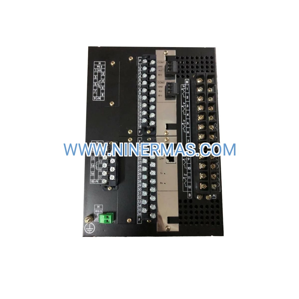
| CT Input Range | 1A or 5A nominal, up to 100x In for fault current |
| VT Input Range | 57-240V AC phase-neutral |
| Protection Functions | 50/51, 50N/51N, 67/67N, 49, 79, 25, 27, 59, 81, 46, 47 |
| Communication Protocols | IEC 61850, Modbus RTU/TCP, DNP3, IEC 60870-5-103 |
| Digital Inputs/Outputs | Configurable up to 32 DI / 24 DO (model dependent) |
| Operating Temperature | -40°C to +70°C |
| Enclosure Rating | IP54 front, IP20 rear (panel-mount) |
| Compliance Standards | IEC 60255, IEEE C37.90, UL/CSA certified |
| Mounting | Flush panel mount, standard 1/2 or 1/4 rack size |
Selection Recommendations: When selecting the F650 configuration, consider system voltage level, CT/VT ratios, required protection functions, communication protocol requirements, available panel space, and environmental conditions. For complex applications involving arc flash mitigation, load shedding, or multi-feeder coordination, consult our protection engineers with single-line diagrams and system parameters for optimized relay settings and configuration files.
Extended Capabilities
- Cybersecurity Features: Role-based access control, encrypted communication, and audit logging comply with IEC 62351 and NERC CIP requirements for critical infrastructure protection.
- Advanced Analytics: Power quality monitoring (harmonics, unbalance, flicker), load profiling, and energy metering support condition-based maintenance and energy management initiatives.
- Remote Access & Diagnostics: Web-based HMI and mobile app connectivity enable remote monitoring, setting changes, and firmware updates, reducing site visit requirements by up to 60%.
- Integration with Asset Management: Seamless data export to PI System, OSIsoft, and enterprise asset management platforms for lifecycle tracking and predictive maintenance analytics.
Delivery, Service & Quality Assurance
Lead Time: Standard catalog models ship within 3-5 business days; custom-configured units require 10-15 business days for factory programming and testing.
Warranty: 12-month comprehensive warranty covering materials and workmanship, with optional extended service agreements available.
Technical Support: Remote commissioning assistance, on-site startup services (region-dependent), and 24/7 technical hotline for critical applications.
Documentation Package: Complete relay manual, protection setting calculation spreadsheet, IEC 61850 ICD/CID files, AutoCAD panel cutout drawings, and wiring diagrams provided with each unit to streamline installation and commissioning.
Quality Certifications: ISO 9001 manufacturing, IEC type-tested, UL/CSA listed, and CE marked for global project compliance.
Frequently Asked Questions (FAQ)
Q: How does the GE F650 feeder protection relay integrate with existing substation automation systems?
A: The F650 supports multiple protocols including IEC 61850 (GOOSE/MMS), Modbus, and DNP3. For IEC 61850 integration, import the relay's ICD file into your system configurator tool; for legacy systems, use Modbus RTU/TCP or DNP3 serial/Ethernet connections. Our engineers provide pre-configured CID files and communication mapping documents.
Q: What is the maximum number of protection zones or feeders one F650 unit can handle?
A: A single F650 unit is designed for one feeder bay with comprehensive protection functions. For multi-feeder applications, deploy one relay per feeder to ensure protection selectivity and reliability. The relay's programmable logic can coordinate with adjacent feeders via GOOSE messaging.
Q: What energy savings or efficiency improvements can be expected with the F650?
A: While the relay itself is a protection device (not an energy-saving device), its advanced metering and load monitoring capabilities enable identification of inefficient equipment, power factor issues, and harmonic sources. Customers report 15-25% reduction in unplanned downtime costs through faster fault detection and diagnostics.
Q: What are the environmental and installation requirements for the F650 relay?
A: The relay operates in -40°C to +70°C ambient temperature with IP54 front panel protection (suitable for indoor substations). For outdoor kiosks or harsh environments, specify conformal coating option. Panel cutout dimensions are standard 1/2 rack (96mm H × 144mm W) or 1/4 rack size; ensure adequate ventilation and avoid direct sunlight exposure.
Q: Can the F650 support remote monitoring and SCADA integration?
A: Yes, the F650 provides Ethernet and serial communication ports supporting IEC 61850 MMS, Modbus TCP, and DNP3 over IP for SCADA integration. Real-time data, alarms, and event logs are accessible via standard protocols. Optional web server enables browser-based monitoring without additional software.
Q: Is firmware upgrade possible, and what cybersecurity features are included?
A: Firmware can be upgraded via front USB port or Ethernet connection using GE's enerVista software. Cybersecurity features include password-protected access (up to 10 user levels), encrypted communication (TLS 1.2), and event logging for compliance with IEC 62351 and NERC CIP standards.
Request Technical Consultation
For detailed protection coordination studies, relay setting files, or project quotations, please provide the following information: project name, application type (utility/industrial/renewable), system voltage and fault level, CT/VT ratios, required protection functions, communication protocol preference, and environmental conditions. Our protection engineers will deliver customized solutions with setting calculations and configuration files within 48 hours.
© 2026 NINERMAS COMPANY LIMITED. All rights reserved. Original Source: https://ninermas.com Contact: sale@ninermas.com | +0086 187 5021 5667


Contact Info
-
Address:22 / F, South Wo Hang building, 148 Wing Lok Street, Sheung Wan, Western District, Hong Kong
-
Phone:+8618750215667
-
Email: