GE F650BFBF1G0HIC6 Digital Bay Controller | Feeder Protection Relay with IEC 61850 | Multilin Series
Description
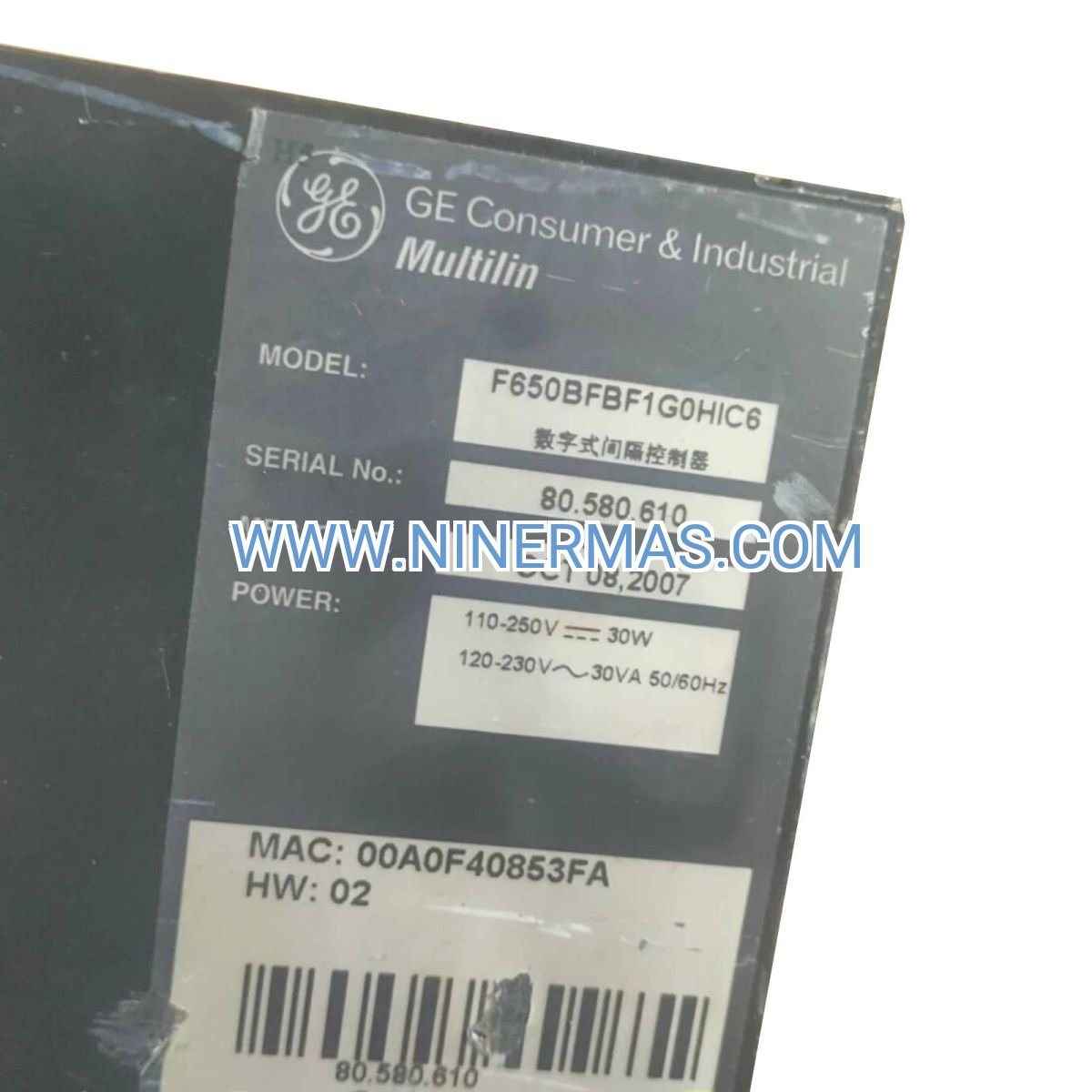
GE F650BFBF1G0HIC6 Digital Bay Controller (Industrial-Grade Feeder Protection System)
The GE F650BFBF1G0HIC6 Digital Bay Controller is an advanced feeder protection and control device engineered for medium-voltage substations, industrial power distribution networks, and utility grid applications. Leveraging GE Multilin's proven protection algorithms and IEC 61850 communication architecture, this relay delivers comprehensive overcurrent, earth fault, directional, and arc flash protection—while enabling seamless integration into modern SCADA and substation automation ecosystems.
Designed for utilities, power generation facilities, industrial plants, and renewable energy installations, the F650 addresses critical challenges including protection coordination complexity, communication protocol fragmentation, limited fault diagnostics, and high maintenance overhead. Its modular design, intuitive HMI, and extensive I/O flexibility make it the preferred choice for consulting engineers, system integrators, and facility operators seeking reliable, future-proof protection solutions.
Built on standardized design with field-proven reliability, the F650BFBF1G0HIC6 offers IEC 61850 native compliance, multi-protocol support (DNP3, Modbus, IEC 60870-5-103), advanced event recording with high-resolution waveform capture, and comprehensive self-diagnostics—ensuring operational continuity, reduced downtime, and simplified lifecycle management. Contact our protection engineers for application-specific configuration, settings coordination, and technical quotations.
Core Functions & Advantages
- Comprehensive Feeder Protection Suite
Integrates ANSI 50/51 overcurrent, 50N/51N ground fault, 67/67N directional protection, 46 negative sequence, 27/59 voltage, and 81 frequency elements—providing multi-layer defense against faults, overloads, and abnormal operating conditions in distribution feeders. - IEC 61850 Native Communication
Supports Edition 1 & 2 GOOSE messaging, MMS client/server, and SCL-based engineering workflows, enabling plug-and-play integration with modern substation automation systems, reduced commissioning time, and enhanced interoperability across multi-vendor environments. - High-Resolution Event & Disturbance Recording
Captures fault waveforms at up to 64 samples/cycle with pre- and post-fault buffers, sequence-of-events (SOE) timestamped to 1 ms resolution, and comprehensive oscillography—accelerating root-cause analysis, protection performance validation, and regulatory compliance reporting. - Flexible I/O & Control Logic
Equipped with configurable digital inputs, form-C output contacts, and programmable logic (FlexLogic™), supporting custom interlocking, auto-reclosing schemes, load shedding, and auxiliary control functions tailored to site-specific operational requirements. - Robust Design for Harsh Environments
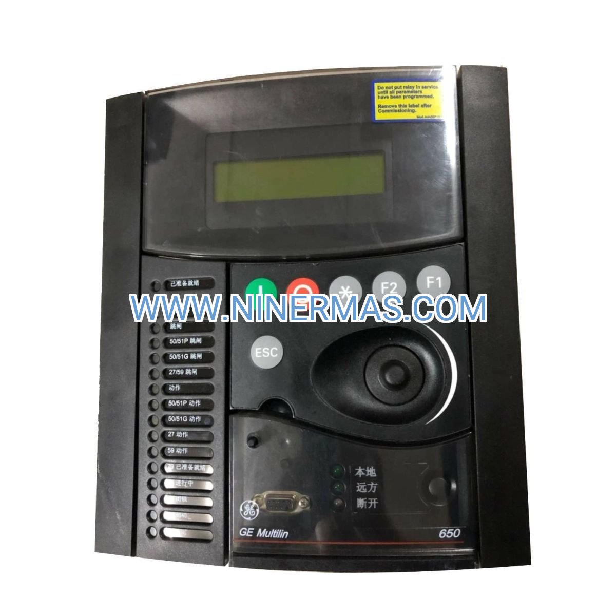
Meets IEC 60255 environmental and EMC standards, operates across -40°C to +85°C ambient range, withstands high vibration and transient overvoltage conditions—ensuring dependable performance in outdoor switchyards, industrial facilities, and remote unmanned substations. - Intuitive Local & Remote HMI
Features front-panel LCD with multi-language support, real-time metering display, alarm annunciation, and remote access via EnerVista™ software suite—simplifying commissioning, troubleshooting, and ongoing maintenance for field technicians and control room operators.
Typical Application Scenarios
The F650BFBF1G0HIC6 is engineered for demanding protection and control applications where reliability, precision, and integration are paramount:
- Utility Distribution Substations
Protects medium-voltage feeders (4.16 kV to 34.5 kV) in municipal and regional grids, coordinating with upstream transmission relays and downstream reclosers to isolate faults rapidly, minimize outage duration, and maintain service continuity for residential and commercial customers. - Industrial Power Distribution & On-Site Generation
Safeguards critical process feeders in petrochemical plants, steel mills, mining operations, and manufacturing facilities—preventing equipment damage from short circuits, ground faults, and motor starting transients while supporting islanded microgrid and cogeneration applications. - Renewable Energy & Distributed Generation
Provides feeder protection and grid interconnection compliance for solar farms, wind parks, and battery energy storage systems (BESS), ensuring adherence to IEEE 1547, IEC 61850-90-7, and utility interconnection standards for anti-islanding, voltage ride-through, and power quality. - Data Centers & Mission-Critical Facilities
Delivers fast, selective fault clearing for UPS-backed distribution systems, emergency generator tie feeders, and dual-source automatic transfer schemes—minimizing arc flash hazards, reducing downtime risk, and supporting NFPA 70E compliance in Tier III/IV data center environments. - Infrastructure & Transportation Systems
Protects traction power substations, airport ground power networks, and rail electrification feeders, meeting stringent safety, availability, and communication requirements for public infrastructure and mass transit applications.
Technical Parameters & Selection Guide
To facilitate engineering design and procurement, we provide standardized electrical, communication, and environmental specifications. Custom configurations are available to match project-specific requirements.
| Parameter | Specification |
|---|---|
| Rated Voltage (AC) | 100–240 V AC / 110–250 V DC (universal power supply) |
| CT Input Range | 1 A or 5 A nominal, 0.01–46 kA fault current capability |
| VT Input Range | 50–240 V AC phase-to-neutral (line-to-line configurable) |
| Protection Functions | ANSI 50/51, 50N/51N, 67/67N, 46, 27/59, 81, 79, 25, 50BF, FlexLogic™ |
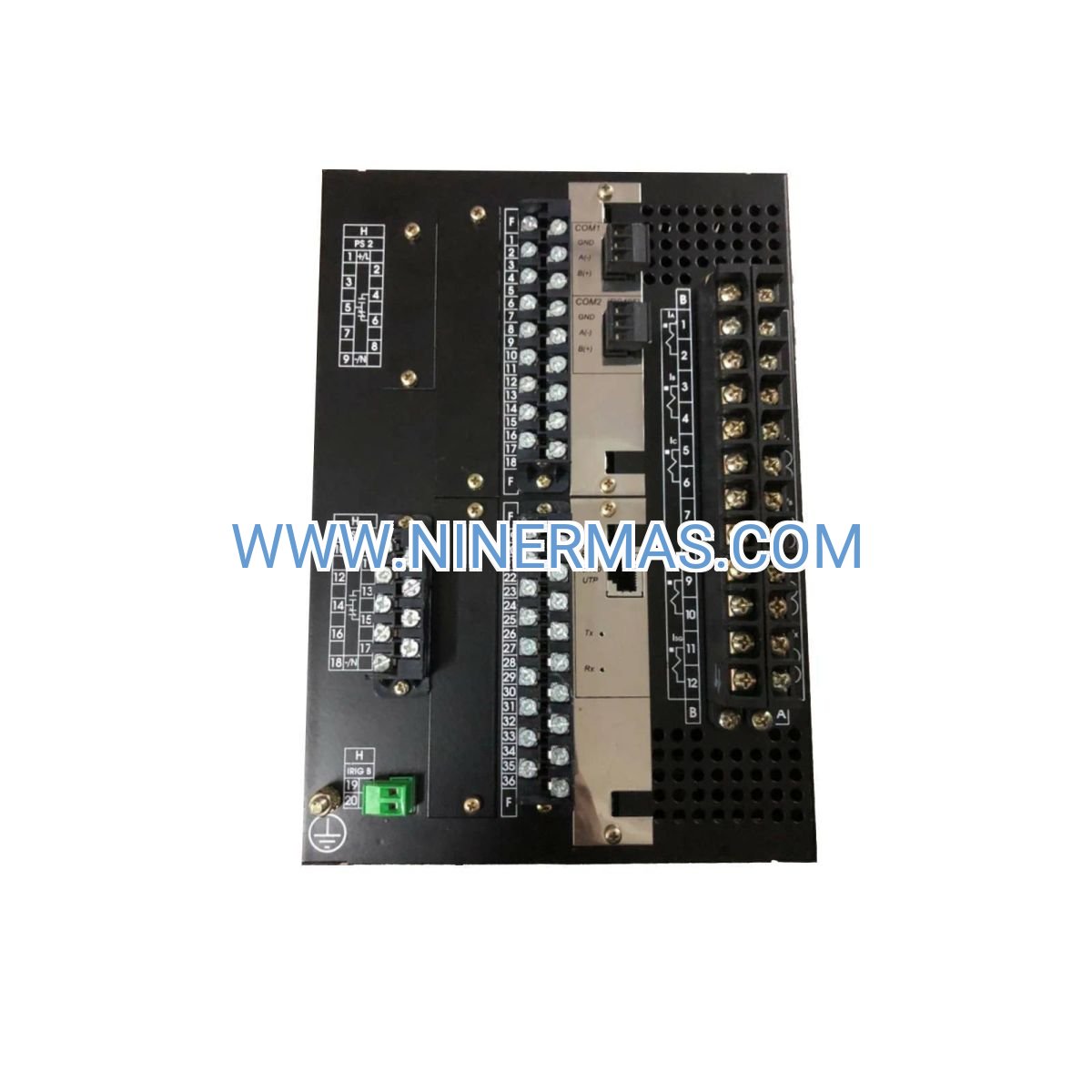
| Communication Protocols | IEC 61850 (GOOSE, MMS), DNP3, Modbus RTU/TCP, IEC 60870-5-103 |
| Ethernet Ports | 2× 10/100Base-TX (RJ45), fiber optic optional |
| Digital Inputs | Up to 16 configurable (wet/dry contact, 24–250 V DC) |
| Output Contacts | Up to 16 Form-C (SPDT), 7 A @ 250 V AC continuous, 30 A make/carry |
| Operating Temperature | -40°C to +85°C (-40°F to +185°F) |
| Enclosure Rating | IP20 (panel mount), IP54 optional for outdoor kiosk |
| Compliance Standards | IEC 60255, IEEE C37.90, UL/cUL, CE, RoHS |
| Dimensions (H×W×D) | Approx. 177 mm × 180 mm × 230 mm (1/4 rack 19" panel mount) |
| Weight | ~1.0 kg (relay module only) |
Selection Recommendations: When specifying the F650BFBF1G0HIC6, consider the following project parameters: feeder voltage class and fault current level, CT/VT ratios and burden, required protection functions and coordination study results, communication architecture (IEC 61850 vs. legacy protocols), I/O count for interlocking and remote control, environmental conditions and enclosure requirements. For assistance with settings calculations, protection coordination, or IEC 61850 SCD file preparation, please provide one-line diagrams and system parameters—our application engineers will recommend optimized configurations and deliver technical proposals.
Extended Capabilities
- Auto-Reclosing & Synchronism Check (ANSI 79, 25): Supports single-shot or multi-shot reclosing sequences with dead-time coordination, synchro-check supervision, and voltage/frequency matching for automatic service restoration on temporary faults.
- Arc Flash Detection & Mitigation: Optional high-speed arc flash sensing inputs enable sub-cycle tripping (<5 ms) when integrated with light/pressure sensors, significantly reducing incident energy and enhancing personnel safety per NFPA 70E and IEEE 1584.
- Power Quality & Energy Metering: Built-in revenue-class metering (IEC 62053, ANSI C12.20 accuracy) tracks kWh, kVARh, demand, power factor, and harmonics—supporting energy management, billing verification, and ISO 50001 compliance.
- Cybersecurity & Role-Based Access: Implements IEC 62351 security extensions, TLS encryption, user authentication, and audit logging to protect against unauthorized access and cyber threats in critical infrastructure environments.
- Redundant Communication & Time Sync: Dual Ethernet ports support PRP/HSR redundancy protocols; IRIG-B, PTP (IEEE 1588), and NTP time synchronization ensure microsecond-level event timestamping for wide-area protection and post-event analysis.
Delivery, Service & Quality Assurance
Lead Time: Standard catalog models (F650BFBF1G0HIC6) typically ship within 4–6 weeks from order confirmation; custom I/O configurations or factory acceptance testing (FAT) may extend delivery to 8–10 weeks depending on scope and factory schedule.
Warranty & Support: All GE Multilin F650 relays include a 12-month manufacturer warranty covering defects in materials and workmanship. Extended warranty, advance replacement, and on-site commissioning services are available upon request. Technical support includes remote diagnostics, firmware updates, and access to EnerVista software suite for configuration and analysis.
Documentation Package: Each relay ships with comprehensive technical documentation including: instruction manual (installation, commissioning, operation), electrical connection diagrams, protection settings worksheets, IEC 61850 ICD/CID files, Modbus/DNP3 register maps, and factory test reports. CAD drawings (DWG/DXF) and 3D STEP models available for panel design integration.
Compliance & Certifications: Manufactured under ISO 9001 quality management system; tested and certified to IEC 60255-27 (product safety), IEC 60255-26 (EMC), IEEE C37.90 (relays and relay systems), UL 508, cUL, CE, and RoHS directives—ensuring global regulatory acceptance and long-term reliability.
Frequently Asked Questions (FAQ)
Q: How does the GE F650BFBF1G0HIC6 integrate with existing substation automation systems?
A: The F650 natively supports IEC 61850 Edition 1 & 2 with GOOSE and MMS services, enabling seamless integration with modern substation automation platforms (e.g., GE Grid Solutions UR series, Siemens SICAM, ABB 615 series). For legacy systems, DNP3 (serial/Ethernet), Modbus RTU/TCP, and IEC 60870-5-103 protocols are available. Configuration is performed via EnerVista software with SCL import/export for IEC 61850 projects. Consult our integration team for multi-vendor interoperability validation and SCD file coordination.
Q: What is the maximum number of protection elements and I/O points supported?
A: The F650BFBF1G0HIC6 configuration includes comprehensive feeder protection functions (50/51, 50N/51N, 67/67N, 46, 27/59, 81, 79, 25) with up to 16 digital inputs and 16 Form-C output contacts as standard. Additional I/O expansion modules can be factory-installed to support complex interlocking, breaker failure, and auxiliary control schemes. FlexLogic™ programmable logic allows custom Boolean equations and timers for site-specific automation.
Q: What are the typical energy savings or operational benefits compared to electromechanical relays?
A: While the F650 is a protection relay (not an energy-saving device per se), it delivers significant operational value: reduced testing and maintenance labor (self-diagnostics, remote access), faster fault clearing (minimizing equipment stress and downtime), improved protection coordination (reducing nuisance trips), and enhanced visibility (metering, event records). Facilities replacing electromechanical relays report 30–50% reduction in annual maintenance costs and improved system availability through predictive diagnostics and remote monitoring.
Q: What are the installation environment requirements and enclosure protection ratings?
A: The F650 relay module is rated IP20 for standard panel-mount indoor installations (control houses, switchgear rooms). Operating temperature range is -40°C to +85°C, suitable for non-climate-controlled environments. For outdoor kiosks or harsh industrial settings, IP54-rated enclosures with environmental sealing, heaters, and ventilation are recommended. The relay meets IEC 60255-21 seismic (Class 2), shock, and vibration standards for utility and industrial applications.
Q: Can the F650 support remote monitoring, data logging, and cybersecurity compliance?
A: Yes. The F650 provides dual Ethernet ports for redundant network connectivity, supports HTTPS/TLS encrypted communication, role-based user access control, and audit logging per IEC 62351 cybersecurity standards. Real-time data (metering, alarms, breaker status) can be accessed via SCADA/HMI systems using IEC 61850 MMS, DNP3, or Modbus protocols. Event records, fault waveforms, and oscillography are retrievable via EnerVista software or automated FTP/SFTP file transfer for centralized asset management and regulatory reporting.
Q: What information is needed for technical selection and quotation?
A: To ensure accurate relay specification and settings coordination, please provide: single-line diagram with voltage levels and fault current data, CT and VT ratios and accuracy class, required protection functions and coordination curves, communication protocol and network architecture (IEC 61850 SCD if available), I/O requirements for interlocking and control, environmental conditions and enclosure preferences, project timeline and delivery location. Our protection engineers will review your application, recommend optimal configuration, and provide detailed technical proposals with pricing and lead time.
Contact & Ordering Information
For detailed selection assistance, custom configuration quotations, or technical support, please contact us with your project details: application description, system voltage and fault levels, protection coordination requirements, communication architecture, I/O count, and delivery schedule. Our application engineers provide one-on-one consultation, settings file preparation, and commissioning support to ensure successful project execution.
© 2026 NINERMAS COMPANY LIMITED. All rights reserved. Original Source: https://ninermas.com | Contact: sale@ninermas.com | +0086 187 5021 5667


Contact Info
-
Address:22 / F, South Wo Hang building, 148 Wing Lok Street, Sheung Wan, Western District, Hong Kong
-
Phone:+8618750215667
-
Email: