GE F650 Digital Bay Controller | Feeder Protection & Monitoring Relay | IEC 61850
Description
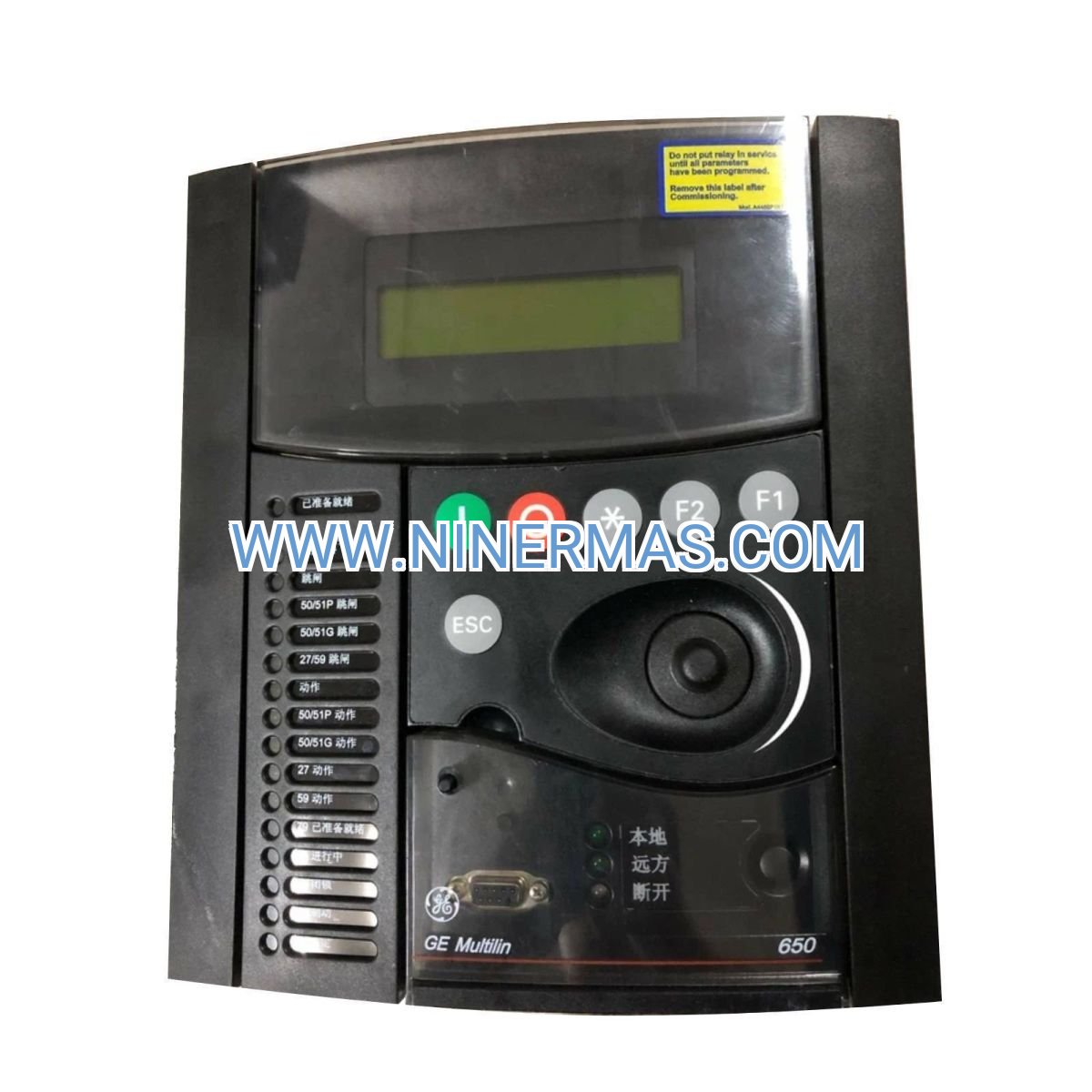
GE F650 Digital Bay Controller (Industrial-Grade Feeder Protection System)
The GE F650 Digital Bay Controller is an advanced multi-function protection relay engineered for medium-voltage feeder circuits, motor feeders, and distribution automation applications. Through integrated microprocessor-based control, comprehensive protection algorithms, and IEC 61850 communication protocols, it delivers real-time monitoring, fault detection, and intelligent control for critical power distribution networks.
Designed for utility substations, industrial plants, renewable energy facilities, and commercial power distribution systems, the F650 addresses challenges including overcurrent faults, ground faults, voltage anomalies, equipment overload, communication protocol incompatibility, and insufficient fault diagnostics. It ensures continuous power reliability while reducing downtime and maintenance costs.
With standardized configuration templates and customizable protection settings, this relay offers rapid commissioning, flexible integration with SCADA systems, advanced event recording capabilities, and multi-language HMI support. Ideal for protection engineers, substation designers, system integrators, and facility managers seeking proven GE Multilin technology. Contact our application engineers for protection coordination studies, settings files, and technical consultation.
Core Functions & Advantages
- Comprehensive Feeder Protection
Provides overcurrent (50/51), ground fault (50N/51N), directional overcurrent (67), voltage (27/59), frequency (81), and thermal overload (49) protection elements with programmable logic and coordination curves to safeguard feeders against diverse fault conditions. - IEC 61850 Substation Automation
Native support for IEC 61850 Edition 2 with GOOSE messaging and MMS services enables seamless integration into modern digital substations, reducing engineering time and improving interoperability with multi-vendor systems. - Advanced Metering & Power Quality
High-accuracy measurement of voltage, current, power (kW, kVAR, kVA), energy (kWh, kVARh), power factor, harmonics (up to 31st order), and demand values supports energy management, billing verification, and power quality analysis. - Flexible Control & Automation
Programmable logic with 512 virtual outputs, 16 timers, and FlexLogic™ equations allows custom automation schemes including auto-reclosing, load shedding, capacitor bank switching, and interlocking without external PLCs. - Comprehensive Fault Recording
Oscillography with up to 1024 samples per cycle, sequence-of-events recording with 1 ms resolution, and fault location algorithms provide detailed post-fault analysis to accelerate troubleshooting and root cause identification. - Robust Design & Reliability
Wide operating temperature range (-40°C to +85°C), conformal coating for harsh environments, redundant power supply inputs, and extensive self-diagnostics ensure dependable operation in demanding industrial and utility applications with minimal maintenance requirements.
Typical Application Scenarios
The GE F650 is engineered for applications demanding high protection reliability, advanced communication capabilities, and comprehensive monitoring:
- Utility Distribution Substations
Protects medium-voltage feeders (4.16 kV to 34.5 kV) in utility networks, coordinating with upstream breakers and downstream reclosers to isolate faults rapidly while maintaining service continuity for unaffected circuits. - Industrial Power Distribution
Safeguards critical feeders in manufacturing plants, petrochemical facilities, mining operations, and data centers where power interruptions result in production losses, equipment damage, or safety hazards requiring fast fault clearing and detailed diagnostics. - Renewable Energy Integration
Monitors and protects feeders connecting solar farms, wind turbines, and battery storage systems to the grid, ensuring compliance with IEEE 1547 interconnection standards and providing anti-islanding, voltage ride-through, and frequency regulation functions. - Commercial & Infrastructure Facilities
Serves hospitals, airports, water treatment plants, and transportation systems requiring uninterrupted power with comprehensive alarm management, remote monitoring via SCADA, and coordinated protection with backup generators and UPS systems.
Technical Parameters & Selection Guide
To facilitate engineering design and product selection, we provide standardized electrical ratings, communication options, and I/O configurations. Custom configurations are available based on project-specific protection requirements.
| Parameter | Specification |
|---|---|
| Rated Voltage | Phase: 90-150 VAC/VDC; Auxiliary: 48-250 VDC |
| Rated Current | 1 A or 5 A nominal (CT secondary) |
| Protection Elements | 50/51, 50N/51N, 67, 27/59, 81, 49, 79, 25, 46, 47 |
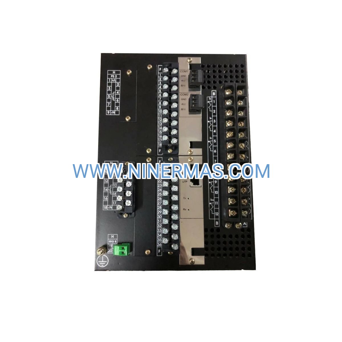
| Communication Protocols | IEC 61850, Modbus RTU/TCP, DNP3, IEC 60870-5-103 |
| Digital Inputs | 16 optically isolated (24-250 VDC) |
| Digital Outputs | 12 Form-A relay contacts (7 A continuous, 30 A make) |
| Analog Inputs | 4 voltage, 4 current (configurable) |
| Operating Temperature | -40°C to +85°C |
| Enclosure Rating | IP52 (front), IP20 (rear) per IEC 60529 |
| Compliance Standards | IEC 60255, IEEE C37.90, UL/cUL, CE |
Selection Recommendations: When specifying the F650, consider CT/VT ratios, required protection functions, communication protocol compatibility with existing SCADA infrastructure, number of I/O points for breaker control and alarming, environmental conditions (temperature, humidity, vibration), and panel mounting space. Provide single-line diagrams, protection coordination studies, and site-specific requirements for engineering support and customized settings files.
Extended Capabilities
- Synchrophasor Measurement (PMU) – Optional IEEE C37.118 phasor measurement unit functionality for wide-area monitoring and grid stability analysis
- Arc Flash Detection – Integration with optical arc flash sensors for ultra-fast fault detection (sub-cycle tripping) to enhance personnel safety
- Cybersecurity Features – Role-based access control, encrypted communications (TLS), audit logging, and compliance with IEC 62351 and NERC CIP standards
- Redundant Ethernet Ports – Parallel Redundancy Protocol (PRP) and High-availability Seamless Redundancy (HSR) per IEC 62439 for mission-critical applications
Delivery, Service & Quality Assurance
Standard catalog models are typically available from stock with delivery within 3-5 business days. Custom-configured units with specific firmware versions, settings files, or extended I/O require 2-4 weeks lead time. All products include a 12-month manufacturer warranty covering defects in materials and workmanship.
Comprehensive technical support includes remote commissioning assistance, protection settings validation, firmware updates, and on-site startup services (subject to location and project scope). Complete documentation packages—including instruction manuals, wiring diagrams, CAD drawings, IEC 61850 ICD files, and Modbus register maps—are provided with each unit to streamline installation, commissioning, and ongoing maintenance.
Frequently Asked Questions (FAQ)
Q: How does the GE F650 Digital Bay Controller integrate with existing substation SCADA systems?
A: The F650 supports multiple communication protocols including IEC 61850 (GOOSE/MMS), Modbus RTU/TCP, DNP3, and IEC 60870-5-103. It features dual Ethernet ports for redundant network connections and can be configured via EnerVista™ software to map data points to your SCADA master. Protocol gateways are available if legacy systems require conversion.
Q: What is the maximum number of protection elements and logic equations the F650 can handle simultaneously?
A: The F650 includes over 40 standard protection elements (overcurrent, voltage, frequency, power, thermal, etc.) and supports up to 512 FlexLogic™ virtual outputs with 16 programmable timers. This allows complex protection schemes, interlocking logic, and automation sequences without external controllers.
Q: Can the F650 feeder protection relay be used for motor protection applications?
A: Yes, the F650 includes thermal overload (49), locked rotor (50/51LR), unbalance (46), and underpower (37) protection elements suitable for medium-voltage motor feeders. Motor-specific settings templates and RTD inputs for winding temperature monitoring are supported in certain hardware configurations.
Q: What are the environmental and installation requirements for the GE F650?
A: The relay operates from -40°C to +85°C with conformal coating for humidity and contaminant resistance. Front panel is IP52 rated; rear terminals are IP20. It mounts in standard 19-inch relay panels (1/4 or 1/2 rack width) and requires 48-250 VDC auxiliary power with <15 W consumption. Ensure adequate ventilation and avoid direct exposure to corrosive gases.
Q: Does the F650 support remote monitoring, firmware updates, and cybersecurity features?
A: Yes, the F650 provides secure remote access via Ethernet with role-based user authentication, encrypted communications (TLS), and audit logging compliant with IEC 62351 and NERC CIP guidelines. Firmware can be updated remotely using EnerVista™ software, and event logs, oscillography, and real-time data are accessible via web browser or SCADA integration.
Q: What technical information is needed to configure and order a GE F650 relay for my project?
A: Please provide: project name and location, feeder voltage and current ratings, CT/VT ratios, required protection functions, communication protocol preferences, number of digital inputs/outputs, auxiliary power supply voltage, environmental conditions, and any specific compliance requirements (e.g., utility standards, arc flash mitigation). Our application engineers will recommend the optimal model code and provide pre-configured settings files.
Contact Us for Technical Support & Quotation
For detailed protection coordination studies, customized settings files, pricing, or technical consultation, please send us the following information: project name, application scenario, system voltage/current levels, CT/PT ratios, number of feeders, communication protocol requirements, and environmental conditions. Our protection engineers will provide one-on-one selection guidance and comprehensive proposals tailored to your substation automation needs.
© 2026 NINERMAS COMPANY LIMITED. All rights reserved. Original Source: https://ninermas.com Contact: sale@ninermas.com | +0086 187 5021 5667


Contact Info
-
Address:22 / F, South Wo Hang building, 148 Wing Lok Street, Sheung Wan, Western District, Hong Kong
-
Phone:+8618750215667
-
Email: