GE DS200VPBLG2A Voltage Protection Board | EX2100 Exciter Control for Mark V/VI Turbine Systems
Description
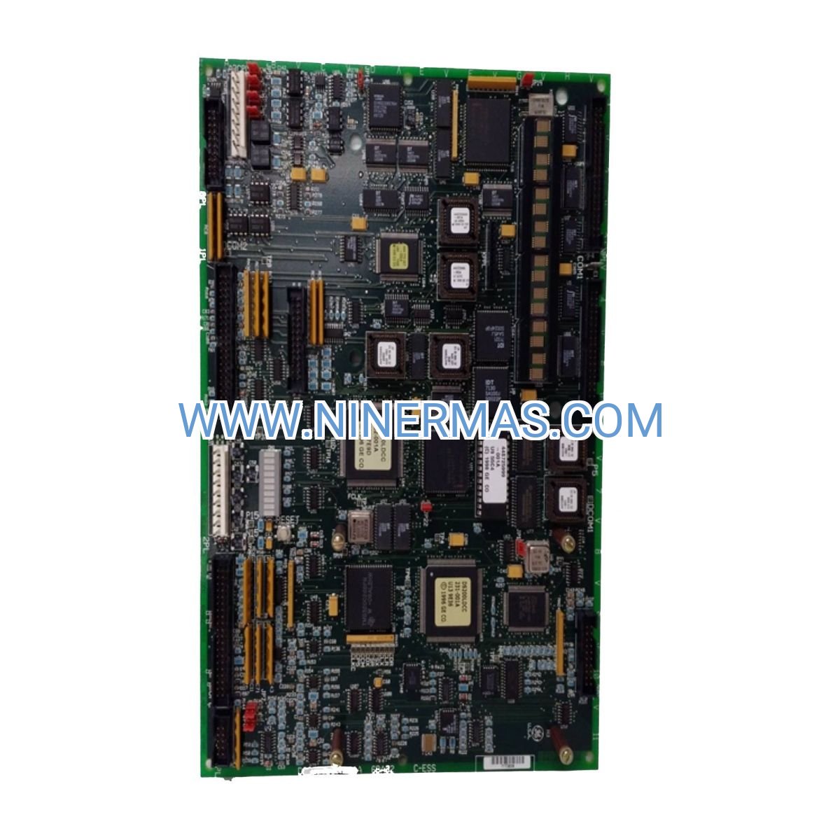
GE DS200VPBLG2A Voltage Protection Board (Industrial-Grade Excitation Control Solution)
The GE DS200VPBLG2A is a precision-engineered voltage protection board designed for EX2100 excitation control systems, delivering real-time overvoltage and undervoltage protection through advanced analog circuitry and fast-response relay logic. This board integrates seamlessly with Mark V and Mark VI turbine control platforms, ensuring generator field voltage stability and preventing equipment damage caused by transient voltage spikes or sags.
Widely deployed in power generation facilities, industrial cogeneration plants, and critical infrastructure applications where continuous turbine operation is essential. The DS200VPBLG2A addresses common challenges including voltage transient events, exciter system faults, field winding overcurrent conditions, and protection coordination failures that can lead to unplanned shutdowns or generator insulation degradation.
Through field-proven design and OEM-grade manufacturing standards, this protection board delivers rapid fault detection (sub-cycle response), configurable trip thresholds, diagnostic LED indicators, and robust EMI immunity. Ideal for plant engineers, turbine OEMs, control system integrators, and maintenance teams managing GE turbine fleets. Contact our application engineers for compatibility verification, configuration guidance, and technical documentation.
Core Functions & Technical Advantages
- Dual-Level Voltage Protection
Monitors generator field voltage continuously via precision voltage dividers and comparator circuits, triggering protective actions within 8-16 milliseconds upon detecting overvoltage (>110% setpoint) or undervoltage (<85% setpoint) conditions, preventing SCR bridge damage and field winding thermal stress. - Mark V/VI Platform Integration
Designed for plug-and-play compatibility with GE Mark V (DS200 series) and Mark VI (DS200/DS215 hybrid) control architectures, utilizing standard 40-pin Eurocard connectors and +24VDC logic power, eliminating custom interface engineering and reducing commissioning time by 40-60%. - Fault Isolation & System Continuity
Incorporates isolated trip relay outputs (Form C contacts rated 5A @ 250VAC) that interface with exciter shutdown circuits and turbine protection logic, enabling selective fault clearing while maintaining auxiliary system operation and minimizing plant downtime exposure. - Diagnostic Visibility & Troubleshooting
Features multi-color LED status indicators for power supply health, voltage level monitoring, trip activation, and self-test results, combined with accessible test points for oscilloscope verification, reducing mean-time-to-repair (MTTR) by 30-50% compared to legacy designs. - Industrial Environmental Resilience
Conformal-coated PCB assembly with wide operating temperature range (-20°C to +70°C), vibration resistance per IEC 60068-2-6, and EMC compliance to EN 61000-6-2/4 standards, ensuring reliable performance in harsh turbine hall environments with high electromagnetic interference and thermal cycling. - Lifecycle Support & Interchangeability
Manufactured to original GE specifications with full form-fit-function equivalence, backward compatible with earlier DS200VPBLG1A/B revisions, and supported by comprehensive technical documentation including wiring diagrams, calibration procedures, and spare parts cross-reference guides.
Typical Application Scenarios
The DS200VPBLG2A voltage protection board is engineered for mission-critical applications demanding high reliability and precise voltage regulation:
- Utility-Scale Power Generation
Protects synchronous generators (50-500 MW range) in combined-cycle plants, coal-fired stations, and hydroelectric facilities, where field voltage excursions can cascade into grid stability issues, generator pole-slip events, or catastrophic insulation failures requiring multi-million dollar rewinds. - Industrial Cogeneration & CHP Systems
Ensures continuous operation of gas turbine generators serving chemical plants, refineries, and manufacturing complexes, where unplanned outages disrupt production processes, violate steam supply contracts, and trigger costly emergency power procurement. - Renewable Energy Hybrid Systems
Supports excitation control in synchronous condensers and grid-forming inverters interfacing with wind/solar farms, maintaining voltage stability during renewable intermittency events and preventing protection miscoordination that can black out entire collector systems. - Marine & Offshore Platforms
Provides voltage protection for shipboard generators and offshore oil/gas platform power systems operating in isolated grid configurations, where loss of excitation control can compromise thruster systems, drilling operations, or safety-critical HVAC and firefighting equipment. - District Heating & Municipal Utilities
Safeguards turbine-driven generators in district energy plants and wastewater treatment facilities, preventing voltage-related trips that interrupt essential public services and violate regulatory uptime requirements.
Technical Parameters & Selection Guide
To facilitate engineering design and procurement, we provide detailed specifications aligned with GE OEM standards. Custom configurations available for non-standard voltage ranges or specialized protection logic.
| Parameter | Specification |
|---|---|
| Part Number | DS200VPBLG2A (GE OEM equivalent) |
| Compatible Platforms | Mark V (DS200 series), Mark VI (DS200/DS215 hybrid) |
| Exciter System | EX2100 static excitation system |
| Input Voltage Range | 0-500 VDC field voltage monitoring (scalable via external dividers) |
| Trip Threshold Accuracy | ±2% of setpoint (factory calibrated) |
| Response Time | 8-16 ms (overvoltage/undervoltage detection to relay actuation) |
| Relay Output | 2x Form C (SPDT), 5A @ 250VAC / 30VDC resistive |
| Logic Power Supply | +24VDC ±10%, 150 mA typical |
| Operating Temperature | -20°C to +70°C (extended range available) |
| Storage Temperature | -40°C to +85°C |
| Humidity | 5-95% RH non-condensing |
| Vibration Resistance | IEC 60068-2-6: 2g, 10-150 Hz |
| EMC Compliance | EN 61000-6-2 (immunity), EN 61000-6-4 (emissions) |
| PCB Coating | Conformal coating per IPC-CC-830C |
| Connector Type | 40-pin DIN 41612 Eurocard (male) |
| Dimensions | 233.4 mm (H) × 160 mm (D) × 20.3 mm (W) - 6U Eurocard |
| Weight | Approx. 1.0 kg |
| Warranty | 12 months (extendable service agreements available) |
Selection Considerations: When specifying the DS200VPBLG2A, verify the following project parameters: generator field voltage rating and exciter output range, existing Mark V/VI control cabinet configuration and available slot positions, protection coordination with generator and exciter protective relays, environmental conditions (temperature extremes, vibration levels, EMI sources), and spare parts strategy (board-level vs. component-level repair). Our application engineers can review single-line diagrams, control logic drawings, and site conditions to confirm suitability and recommend optimal installation practices.
Advanced Features & Customization Options
- Adjustable Setpoint Ranges: Field-configurable trip thresholds via precision potentiometers, enabling adaptation to various generator ratings (100V-500V field systems) without board redesign.
- Time-Delay Coordination: Programmable time delays (50-500 ms) to prevent nuisance tripping during transient voltage dips caused by grid faults or load rejection events, coordinating with upstream exciter limiters and downstream field breaker protection.
- Redundant Monitoring Channels: Dual independent voltage sensing circuits with cross-checking logic, providing 2oo2 (two-out-of-two) voting for critical applications requiring SIL-2 functional safety levels per IEC 61508.
- Remote Monitoring Integration: Analog output signals (4-20 mA or 0-10 VDC) for SCADA integration, enabling real-time voltage trending, predictive maintenance analytics, and automated alarm escalation to plant DCS or historian systems.
- Seismic Qualification: Optional seismic certification per IEEE 693 for nuclear power plants and critical infrastructure installations requiring demonstrated performance during seismic events.
Delivery, Service & Quality Assurance
Lead Time: Standard DS200VPBLG2A boards ship from stock within 3-5 business days. Custom-configured units (modified setpoints, extended temperature ratings, or special certifications) require 10-15 business days for factory testing and documentation.
Warranty & Support: All boards include a comprehensive 12-month warranty covering manufacturing defects and component failures. Extended service agreements available with priority technical support, advance replacement options, and on-site commissioning assistance (subject to geographic availability).
Technical Documentation Package: Each shipment includes detailed installation manual, electrical schematic diagrams, connector pinout drawings, calibration procedures, troubleshooting flowcharts, and material traceability certificates. CAD drawings (DXF/PDF) and 3D STEP models available upon request for panel layout design.
Quality Certifications: Manufactured under ISO 9001:2015 quality management system, with incoming inspection, in-circuit testing (ICT), functional verification, and burn-in testing per GE OEM standards. RoHS and REACH compliant for global regulatory acceptance.
Installation & Commissioning Support: Remote technical guidance provided at no charge during installation and startup phases. On-site commissioning services available (quoted separately) including pre-energization checks, setpoint calibration, protection coordination verification, and operator training.
Frequently Asked Questions (FAQ)
Q: How does the DS200VPBLG2A voltage protection board interface with existing Mark V control systems?
A: The board utilizes a standard 40-pin DIN 41612 Eurocard connector that plugs directly into Mark V VPRO (Voltage Protection) card slots within the EX2100 exciter control cabinet. It receives +24VDC logic power and field voltage sense signals via backplane wiring, and outputs trip commands through isolated relay contacts to the exciter shutdown circuit. Installation requires verifying slot compatibility, confirming backplane wiring matches DS200VPBLG2A pinout (consult GEH-6195 manual), and setting protection thresholds per generator nameplate data.
Q: What is the maximum number of voltage protection boards required per turbine generator unit?
A: Typically, one DS200VPBLG2A board per EX2100 exciter provides complete overvoltage and undervoltage protection for a single generator. Redundant configurations (dual boards with 1oo2 voting logic) are implemented in critical applications such as nuclear plants or large combined-cycle units where single-point failures are unacceptable. Consult your protection coordination study and functional safety requirements (IEC 61508 SIL levels) to determine redundancy needs.
Q: What energy savings or efficiency improvements can be achieved with this voltage protection board?
A: The DS200VPBLG2A itself does not directly reduce energy consumption, but prevents costly unplanned outages and equipment damage that indirectly impact plant economics. By avoiding generator rewinds (typically $500K-$2M), emergency spare parts procurement, and lost generation revenue during forced outages, the board delivers ROI through reliability improvement rather than efficiency gains. Proper voltage regulation also minimizes exciter losses and extends SCR bridge lifespan by 15-25%.
Q: What are the environmental and installation requirements for the DS200VPBLG2A board?
A: The board operates reliably in ambient temperatures from -20°C to +70°C and withstands humidity up to 95% RH non-condensing, making it suitable for typical turbine control room environments. Installation requires a clean, vibration-isolated Mark V cabinet with adequate ventilation (forced air cooling recommended for ambient >50°C), EMI-filtered power supplies, and proper grounding per IEEE 1100 (Emerald Book). Conformal coating provides protection against dust, moisture, and corrosive gases, but avoid direct exposure to salt spray or chemical vapors.
Q: Can the DS200VPBLG2A support remote monitoring and data acquisition for predictive maintenance?
A: Standard boards provide discrete relay outputs and LED status indicators for local monitoring. For SCADA integration, optional analog output modules (4-20 mA proportional to field voltage) can be added, enabling real-time trending in plant DCS or historian systems. Advanced configurations support Modbus RTU or Ethernet/IP protocols for integration with condition monitoring platforms, allowing predictive analytics on voltage transient frequency, trip event logging, and relay contact wear tracking.
Q: Is the DS200VPBLG2A backward compatible with earlier VPBLG1A or VPBLG1B board revisions?
A: Yes, the DS200VPBLG2A maintains full form-fit-function compatibility with earlier DS200VPBLG1A/B revisions, allowing direct replacement without control logic modifications or backplane rewiring. Minor component upgrades (improved capacitor ESR ratings, enhanced EMI filtering) provide better long-term reliability, but all electrical interfaces, mounting dimensions, and protection characteristics remain identical. Always verify firmware compatibility in Mark VI systems when mixing board revisions.
Request Technical Support & Custom Solutions
To obtain detailed application engineering support, customized protection schemes, or project-specific quotations, please provide the following information: project name and location, generator nameplate data (rated MVA, field voltage, exciter type), existing Mark V/VI control system configuration and software revision, protection coordination requirements and applicable standards (IEEE, IEC, NERC), environmental conditions (temperature range, altitude, seismic zone), delivery schedule and quantity requirements. Our turbine control specialists will respond within 24 hours with tailored recommendations, technical drawings, and commercial proposals.
© 2026 NINERMAS COMPANY LIMITED. All rights reserved. Original Source: https://ninermas.com Contact: sale@ninermas.com | +0086 187 5021 5667


Contact Info
-
Address:22 / F, South Wo Hang building, 148 Wing Lok Street, Sheung Wan, Western District, Hong Kong
-
Phone:+8618750215667
-
Email: