Description
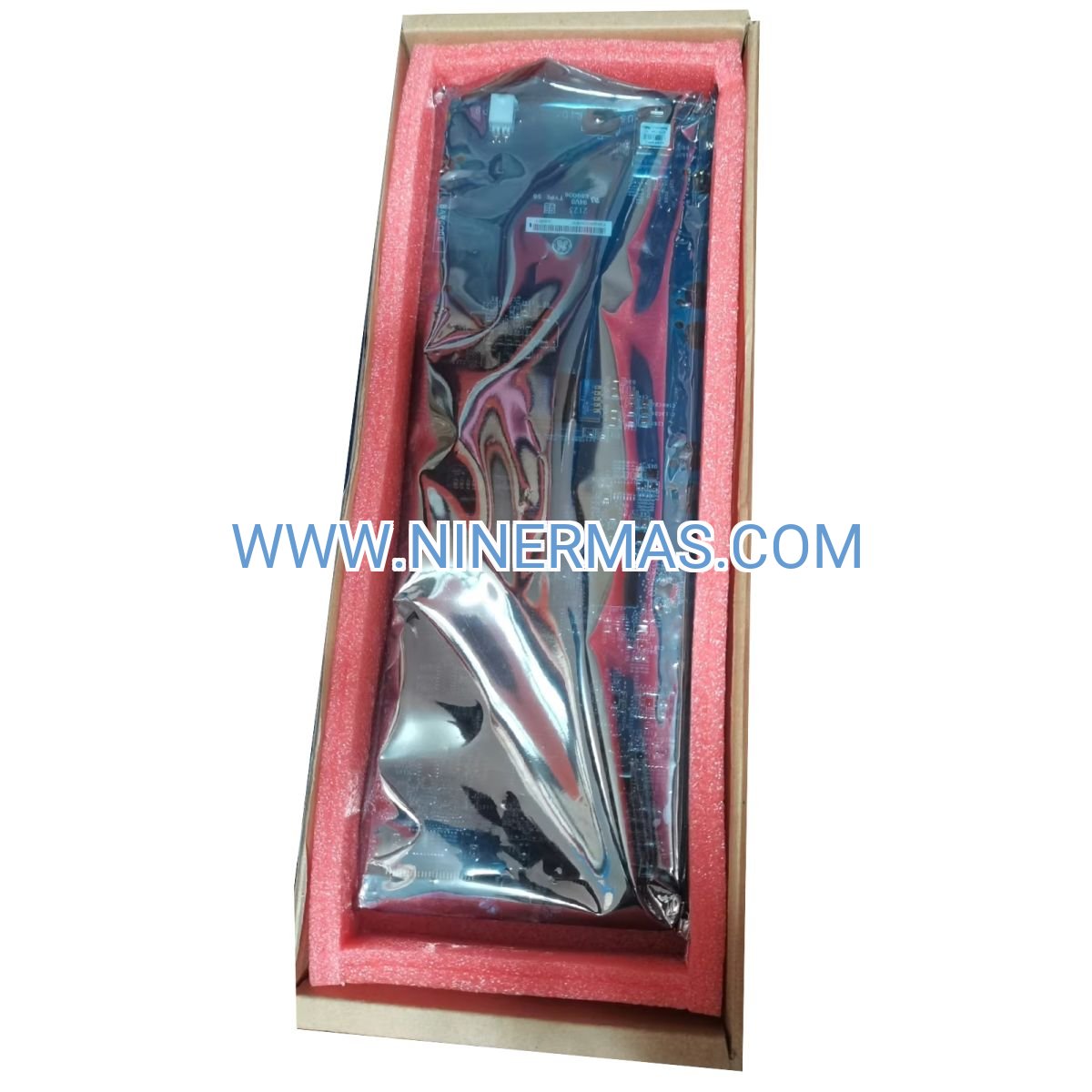
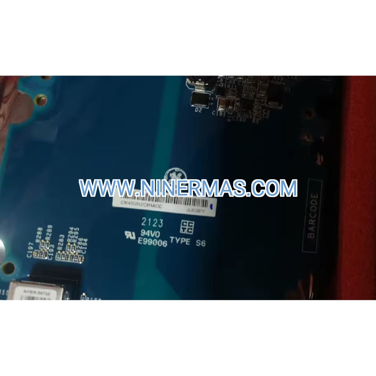
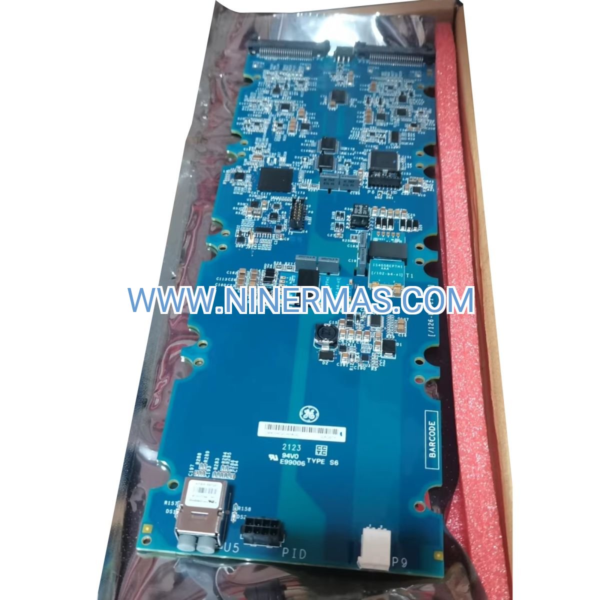
GE CM400RGICH1ADC IGBT Power Module – Industrial-Grade High-Current Switching Solution
The GE CM400RGICH1ADC is a dual IGBT power module engineered for demanding industrial control applications requiring precise, high-efficiency power conversion. Through advanced semiconductor design combining 400-ampere continuous current capability with 1200-volt blocking voltage, this module delivers reliable switching performance in variable frequency drives, servo inverters, renewable energy systems, and uninterruptible power supplies.
Designed for integration into three-phase bridge topologies and multi-level converter architectures, the CM400RGICH1ADC addresses critical challenges in motor control systems: minimizing conduction losses during steady-state operation, reducing electromagnetic interference through optimized switching transitions, and maintaining thermal stability under continuous high-power cycling. Its dual-pack configuration with integrated anti-parallel freewheeling diodes simplifies circuit design while ensuring bidirectional current flow capability essential for regenerative braking and four-quadrant operation.
Ideal for design engineers, system integrators, OEM manufacturers, and maintenance teams managing industrial automation infrastructure, this module combines proven GE semiconductor technology with comprehensive protection features and thermal management capabilities. Our application engineering team provides selection guidance, gate drive circuit recommendations, and thermal analysis support to ensure optimal integration into your power conversion system.
Core Capabilities & Engineering Advantages
Optimized Conduction Efficiency
With typical collector-emitter saturation voltage of 2.5V at rated 400A current, the module achieves conduction losses below 1kW per switch position, enabling overall inverter efficiency exceeding 97% in motor drive applications. This low VCE(sat) characteristic reduces heat generation in the semiconductor junction, extending operational lifespan and lowering cooling system requirements compared to earlier-generation IGBT technologies.
High-Speed Switching Performance
Turn-on time of 150 nanoseconds and turn-off time of 350 nanoseconds enable PWM frequencies up to 20kHz, providing superior motor current waveform quality with reduced torque ripple and acoustic noise. Fast switching transitions minimize overlap losses during commutation while maintaining controlled dv/dt characteristics that protect motor insulation systems and reduce common-mode EMI in variable speed drive installations.
Integrated Freewheeling Diode Architecture
Each IGBT position incorporates an anti-parallel fast-recovery diode with soft reverse recovery characteristics (trr < 200ns), eliminating the need for external discrete diodes and reducing system component count. The co-packaged diode design ensures matched thermal characteristics and minimizes parasitic inductance in the commutation loop, critical for reliable operation at high switching frequencies and inductive load conditions.
Robust Fault Tolerance
Short-circuit withstand capability of 10 microseconds at rated voltage provides essential protection margin for gate drive fault detection and shutdown sequencing. The module's wide safe operating area (SOA) encompasses both reverse-bias and forward-bias conditions, ensuring reliable operation during load transients, regenerative braking events, and DC bus voltage fluctuations typical in industrial power distribution networks.
Advanced Thermal Management Design
Isolated copper base plate with thermal resistance of 0.083°C/W per IGBT facilitates efficient heat transfer to forced-air or liquid-cooled heatsink assemblies. The electrically isolated mounting surface simplifies grounding architecture in multi-module configurations while maintaining creepage and clearance distances compliant with IEC 61800-5-1 safety standards for adjustable speed electrical power drive systems.
Industrial-Grade Package Construction
Screw-terminal power connections accommodate wire sizes up to 35mm² (2 AWG) for low-resistance DC bus and AC output connections, while spring-clamp gate terminals ensure reliable signal integrity in high-vibration environments. The module's compact 140mm × 107mm footprint enables high power density inverter designs while maintaining adequate spacing for high-voltage isolation requirements in 690V AC drive applications.
Target Application Environments
Variable Frequency Drive Systems (VFD)
The CM400RGICH1ADC serves as the primary switching element in three-phase voltage-source inverters for AC induction motors and permanent magnet synchronous motors ranging from 75kW to 250kW. In HVAC chiller systems, the module's efficiency characteristics reduce annual energy consumption by 25-35% compared to across-the-line motor starters, while in industrial pump and fan applications, precise speed control eliminates mechanical throttling losses and extends equipment service life through soft-start acceleration profiles.
Servo Drive Inverter Stages
High-performance motion control systems for CNC machine tools, packaging equipment, and robotic manipulators benefit from the module's fast switching capability and low output current distortion. When paired with high-resolution encoders and advanced field-oriented control algorithms, the CM400RGICH1ADC enables position accuracy within ±0.01mm and velocity regulation better than 0.1% across the full speed range, meeting the stringent requirements of semiconductor manufacturing and precision assembly operations.
Renewable Energy Power Conversion
Solar photovoltaic inverter applications from 50kW to 150kW utilize the module's wide input voltage range and high-frequency switching to achieve maximum power point tracking (MPPT) efficiency exceeding 99%. In wind turbine converter systems, the IGBT's robust SOA characteristics handle the dynamic power fluctuations inherent in variable wind conditions, while the integrated diodes provide reliable grid-side rectification during generator overspeed events and emergency braking sequences.
Uninterruptible Power Supply Topologies
Online double-conversion UPS systems rated 50kVA to 200kVA employ the CM400RGICH1ADC in both rectifier and inverter stages, ensuring continuous clean power delivery to data centers, telecommunications facilities, and medical imaging equipment. The module's low conduction losses minimize battery discharge rates during utility outages, while its fast switching capability maintains output voltage total harmonic distortion (THD) below 3% across linear and nonlinear load conditions.
Industrial Induction Heating Systems
Medium-frequency induction heating applications for metal hardening, brazing, and melting processes leverage the module's high current density and thermal cycling capability. Operating at frequencies from 1kHz to 10kHz with resonant load circuits, the CM400RGICH1ADC delivers precise power control for repeatable metallurgical processes while withstanding the harsh electromagnetic environment characteristic of induction heating installations.
Technical Specifications & Selection Parameters
To facilitate system design and component selection, the following parameters define the CM400RGICH1ADC's electrical and thermal characteristics under standard test conditions:
| Parameter | Symbol | Rating | Test Conditions |
|---|---|---|---|
| Collector-Emitter Voltage | VCES | 1200V | VGE = 0V, Tj = 25°C |
| Continuous Collector Current | IC | 400A | Tc = 25°C |
| Pulsed Collector Current | ICM | 800A | tp = 1ms |
| Gate-Emitter Voltage | VGES | ±20V | Continuous |
| Collector-Emitter Saturation Voltage | VCE(sat) | 2.5V typ | IC = 400A, VGE = 15V |
| Gate Threshold Voltage | VGE(th) | 5.5V typ | IC = 10mA, Tj = 25°C |
| Input Capacitance | Cies | 28nF typ | VCE = 25V, VGE = 0V |
| Turn-On Delay Time | td(on) | 0.15μs typ | Inductive load, VGE = ±15V |
| Turn-Off Delay Time | td(off) | 0.35μs typ | Inductive load, VGE = ±15V |
| Short-Circuit Withstand Time | tsc | 10μs | VCE ≤ 800V, Tj ≤ 150°C |
| Thermal Resistance Junction-Case | Rth(j-c) | 0.083°C/W | Per IGBT |
| Operating Junction Temperature | Tj | -40°C to +150°C | Continuous operation |
| Storage Temperature | Tstg | -40°C to +125°C | Non-operating |
| Isolation Voltage | Viso | 2500V AC | Terminal to base, 1 minute |
| Module Weight | — | 500g approx | — |
Selection Guidance for System Designers
When specifying the CM400RGICH1ADC for your application, consider the following design parameters: peak motor current including starting transients (typically 150-200% of rated current), DC bus voltage range accounting for line voltage variations and regenerative overvoltage (recommend 20% margin below VCES rating), ambient temperature and available cooling capacity (forced air flow rate or liquid coolant temperature), switching frequency requirements balanced against efficiency targets, and electromagnetic compatibility constraints. For assistance with thermal modeling, gate drive circuit design, or snubber network optimization, our application engineering team can review your system architecture and provide customized recommendations based on your specific operating conditions.
System Integration & Circuit Design Recommendations
Gate Drive Circuit Requirements
Optimal switching performance requires a dedicated isolated gate driver capable of delivering ±15V gate-emitter voltage with minimum 2A peak source/sink current. The driver circuit should incorporate desaturation detection monitoring VCE during on-state conduction, with fault response time under 2 microseconds to ensure protection within the module's 10μs short-circuit rating. Recommended gate resistor values range from 2.2Ω to 4.7Ω for turn-on (Rg-on) and 1.0Ω to 2.2Ω for turn-off (Rg-off), with final values optimized through oscilloscope measurement of switching waveforms to balance turn-on losses, turn-off losses, and dv/dt stress on motor insulation.
DC Bus Capacitor Bank Design
Three-phase bridge inverter configurations require low-ESR DC link capacitors positioned within 100mm of module power terminals to minimize stray inductance and voltage overshoot during commutation. For 1200V-rated systems, specify film capacitors (polypropylene or polyester) with minimum capacitance of 200μF per 100kVA inverter power rating, voltage rating of 1.3× maximum DC bus voltage, and ripple current capability exceeding 1.5× RMS load current. In applications with regenerative braking or frequent load transients, increase capacitance by 50% to limit DC bus voltage ripple below 5% and reduce capacitor thermal stress.
Thermal Management System Considerations
Heatsink selection must account for total power dissipation including IGBT conduction losses, switching losses, and diode losses across the full operating cycle. For continuous 400A operation at 10kHz switching frequency, typical total losses per module approach 1.2-1.5kW, requiring heatsink thermal resistance below 0.04°C/W to maintain junction temperature under 125°C with 40°C ambient. Apply thermal interface material (silicone grease or phase-change pad) with thermal conductivity >3 W/m·K and thickness <100μm to minimize contact resistance between module base and heatsink surface. In high-reliability applications, embed NTC thermistor sensors in the heatsink assembly for continuous temperature monitoring and predictive maintenance algorithms.
Electromagnetic Compatibility Measures
High-frequency switching generates common-mode and differential-mode electromagnetic interference requiring careful PCB layout and filtering. Route gate drive signal traces as differential pairs with controlled impedance, maintain minimum 8mm creepage distance between high-voltage and low-voltage circuits, and implement ground plane segmentation to separate noisy power grounds from sensitive control grounds. Install common-mode chokes on motor output cables (minimum 100μH inductance) and differential-mode capacitors (0.1-1.0μF, X2-rated) at inverter output terminals to attenuate conducted emissions below EN 55011 Class A limits. For installations near sensitive instrumentation, consider shielded motor cables with 360° shield termination at both drive and motor ends.
Protection Circuit Implementation
Comprehensive fault protection requires coordination between hardware and software safeguards. Implement hardware-based overcurrent detection using current sensors (Hall-effect or current transformer) with analog comparator circuits triggering gate shutdown within 3-5 microseconds of fault detection. Software-based protection algorithms should monitor DC bus overvoltage/undervoltage (±10% thresholds), heatsink overtemperature (>85°C warning, >95°C shutdown), and phase loss conditions through current imbalance detection. After fault shutdown, enforce minimum 500ms dead time before restart attempts to allow energy dissipation in snubber circuits and DC bus discharge through bleeder resistors.
Frequently Asked Questions (Technical Support)
Q: What is the recommended gate drive voltage for the CM400RGICH1ADC, and can I use +15V/0V instead of ±15V?
A: The optimal gate drive voltage is +15V for turn-on and -15V for turn-off. While +15V/0V operation is technically possible, it significantly increases turn-off time and switching losses due to slower gate discharge through the internal gate-emitter resistance. The negative turn-off voltage actively removes stored charge from the gate capacitance, reducing tail current and minimizing overlap losses during commutation. Additionally, -15V gate bias improves noise immunity against false turn-on from dv/dt transients in high-frequency switching environments. For maximum reliability and efficiency, we strongly recommend ±15V gate drive implementation using isolated DC-DC converters rated for minimum 2.5kV isolation.
Q: Can multiple CM400RGICH1ADC modules be paralleled to achieve higher current ratings, and what precautions are necessary?
A: Yes, parallel operation is feasible with careful design attention to current sharing. Key requirements include: (1) matched gate drive timing within ±50 nanoseconds using identical driver circuits and equal trace lengths, (2) symmetrical DC bus and AC output conductor routing to equalize stray inductance below 20nH difference between parallel paths, (3) individual current-sharing inductors (1-2μH, air-core) in each module's collector circuit to force equal current distribution during transients, and (4) thermal coupling between modules mounted on common heatsink to promote temperature equalization. Derate the total parallel current to 90% of the sum of individual ratings to account for inevitable parameter variations. For applications requiring >800A, consider higher-current single modules to reduce complexity and improve reliability.
Q: What snubber circuit configuration is recommended for motor drive applications with long cable runs?
A: For motor cables exceeding 50 meters, implement a two-stage approach: (1) RCD snubber across each IGBT consisting of 0.1μF/1600V film capacitor, 10Ω/5W resistor, and ultrafast recovery diode (trr <50ns) to clamp voltage overshoot from module parasitic inductance, and (2) RC snubber at motor terminals (0.22μF capacitor + 47Ω resistor per phase) to dampen cable resonance and reduce reflected wave voltage stress on motor insulation. The integrated anti-parallel diodes in the CM400RGICH1ADC have soft recovery characteristics (di/dt <200A/μs), minimizing snubber requirements compared to older IGBT generations. Verify snubber effectiveness by measuring voltage overshoot under worst-case conditions (maximum cable length, minimum load current) and ensure peak voltage remains below 80% of VCES rating.
Q: How does the CM400RGICH1ADC compare to newer silicon carbide (SiC) MOSFET modules for VFD applications?
A: The comparison depends on your specific application requirements and priorities. SiC MOSFETs offer superior performance at switching frequencies above 50kHz, with switching losses 50-70% lower than silicon IGBTs, enabling higher efficiency in compact, high-frequency converter designs. However, for traditional industrial VFD applications operating at 4-20kHz, the CM400RGICH1ADC provides several advantages: (1) significantly lower cost per ampere (typically 40-60% less than equivalent SiC modules), (2) simpler gate drive requirements (±15V vs. +20V/-5V for SiC), (3) more forgiving short-circuit protection (10μs vs. 3-5μs for SiC), and (4) proven long-term reliability data spanning decades of industrial deployment. For retrofit projects replacing existing IGBT-based drives or cost-sensitive applications where switching frequency below 20kHz is acceptable, silicon IGBT technology remains the optimal choice.
Q: What DC bus capacitance is required for a 150kW three-phase inverter using the CM400RGICH1ADC?
A: For a 150kW inverter operating from 690V AC input (approximately 970V DC bus), the minimum DC link capacitance should be 300μF (calculated as 200μF per 100kVA). Select low-ESR film capacitors rated for 1300V DC with ripple current capability exceeding 250A RMS. In practice, we recommend 400-500μF total capacitance distributed across multiple capacitor units to improve reliability through redundancy and reduce ESR. Position capacitors symmetrically around the IGBT modules with low-inductance laminated bus bars (<50nH total loop inductance) to minimize voltage overshoot during switching transients. For applications with frequent regenerative braking (elevators, cranes, test dynamometers), increase capacitance to 600-800μF to absorb regenerated energy and limit DC bus voltage rise below the overvoltage protection threshold (typically 1100V for 690V AC systems).
Q: Does the CM400RGICH1ADC require isolated gate power supplies for each IGBT in a three-phase bridge?
A: Yes, each of the six IGBTs in a standard three-phase bridge configuration requires an isolated gate power supply due to the different emitter reference potentials. The three high-side IGBTs have emitters connected to the bridge midpoints (motor phase outputs), which swing between DC+ and DC- during operation, while the three low-side IGBTs have emitters connected to DC-. You'll need six isolated ±15V gate supplies, each rated for minimum 2W continuous power (accounting for gate drive losses and auxiliary circuits). Practical implementation options include: (1) six individual isolated DC-DC converters with >2.5kV isolation voltage, (2) three dual-output isolated converters serving one high-side and one low-side IGBT each, or (3) a multi-output isolated power supply specifically designed for IGBT gate drive applications. Ensure each isolated supply has adequate transient response to maintain regulation during high-frequency gate switching and sufficient isolation voltage to withstand the full DC bus voltage plus transient overvoltage margin.
Q: What are the typical failure modes for IGBT modules, and how can I implement condition monitoring for predictive maintenance?
A: Common IGBT failure mechanisms include: (1) bond wire fatigue from thermal cycling (manifests as increased VCE(sat) and thermal resistance), (2) solder layer degradation causing thermal interface failure, (3) gate oxide breakdown from overvoltage transients, and (4) latch-up from excessive di/dt or dv/dt stress. Implement predictive maintenance by monitoring: VCE(sat) during conduction using precision measurement circuits (increasing trend indicates bond wire degradation), junction temperature via embedded NTC thermistors (rising temperature at constant load suggests thermal interface degradation), gate leakage current (increasing leakage indicates gate oxide stress), and switching waveform characteristics using high-speed data acquisition (changes in turn-on/turn-off times reveal parameter drift). Establish baseline measurements during commissioning and trigger maintenance alerts when parameters deviate >15% from baseline values. Typical service life exceeds 100,000 operating hours when junction temperature is maintained below 125°C and thermal cycling range is limited to <80°C ΔTj.
Quality Assurance & Technical Support Services
Every GE CM400RGICH1ADC IGBT module undergoes rigorous factory testing including VCES blocking voltage verification, VCE(sat) characterization at rated current, gate threshold voltage measurement, and high-potential isolation testing to ensure compliance with published specifications. Our quality management system maintains full traceability from semiconductor wafer fabrication through final module assembly, with serialized documentation available for critical applications requiring failure analysis support.
Warranty Coverage: Standard 12-month manufacturer warranty covers defects in materials and workmanship under normal operating conditions within published ratings. Extended warranty programs (24-36 months) are available for OEM customers and critical infrastructure applications. Warranty claims require documentation of operating conditions including junction temperature logs, gate drive waveforms, and fault event records to facilitate root cause analysis.
Application Engineering Support: Our technical team provides complimentary pre-sales consultation including gate drive circuit design review, thermal simulation using finite element analysis (FEA), EMC filter design guidance, and parallel operation feasibility assessment. Post-sales support includes troubleshooting assistance, oscilloscope waveform interpretation, and on-site commissioning support for complex multi-module installations (travel charges may apply based on location).
Documentation Package: Each module ships with comprehensive technical documentation including detailed datasheet with characteristic curves, application note covering gate drive design and thermal management, mechanical drawings with mounting hole dimensions and terminal specifications, and reliability data including MTBF calculations and thermal cycling test results.
Procurement & Delivery Information
To obtain detailed quotations, customized selection guidance, or technical specifications for your specific application, please provide our engineering team with the following project parameters: application type (VFD, servo drive, UPS, renewable energy, etc.), motor power rating and voltage class, DC bus voltage range, required switching frequency, ambient temperature and cooling method (forced air CFM or liquid coolant flow rate), quantity requirements and delivery timeline, and any special certifications needed (UL, CE, CCC, etc.).
Our specialists will respond within 24 hours with tailored recommendations including module selection, gate driver compatibility, thermal management solutions, and complete bill of materials for your power conversion system. For urgent retrofit projects or emergency replacement requirements, expedited processing and express shipping options are available to minimize downtime in critical industrial operations.
© 2026 NINERMAS COMPANY LIMITED. All rights reserved.
Original Source: https://ninermas.com
Contact: sale@ninermas.com | +0086 187 5021 5667


Contact Info
-
Address:22 / F, South Wo Hang building, 148 Wing Lok Street, Sheung Wan, Western District, Hong Kong
-
Phone:+8618750215667
-
Email: