Description
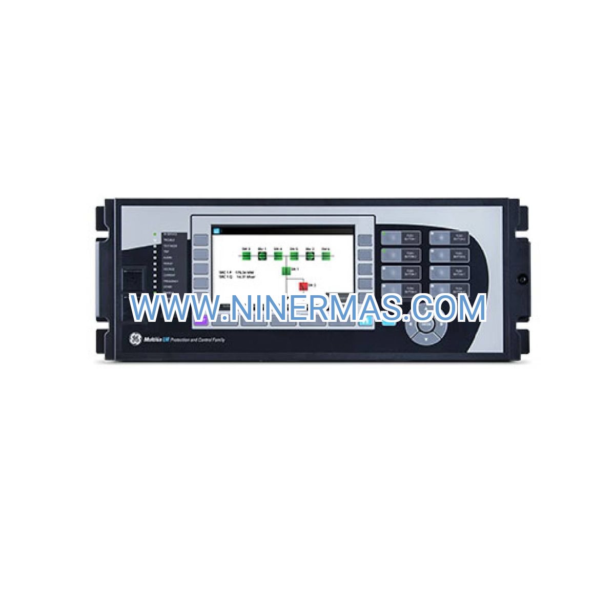
GE B90-B9M-15C Line Differential Relay (Industrial-Grade EHV Transmission Protection System)
The GE B90-B9M-15C Line Differential Relay is an industrial-grade protection device engineered for extra-high-voltage (EHV) transmission line applications. Through advanced current differential algorithms combined with integrated distance protection elements, this relay achieves sub-cycle fault detection and isolation across transmission corridors operating from 69kV to 500kV. Designed for utility substations, renewable energy interconnections, and critical grid infrastructure, the B90 delivers unmatched speed, selectivity, and reliability in protecting high-capacity power transmission assets.
Suitable for electric utilities, independent power producers, industrial power distribution networks, and substation automation projects, the B90 addresses challenges including high-resistance fault detection, CT saturation immunity, multi-terminal line coordination, and bidirectional power flow protection. With dual-redundant fiber optic communication channels and comprehensive backup protection functions, this relay minimizes system downtime and prevents cascading grid failures.
Built on proven GE Multilin technology with field-tested algorithms and modular hardware architecture, the B90-B9M-15C offers flexible configuration options, extensive communication protocol support (IEC 61850, DNP3, Modbus), and integrated synchrophasor measurement capabilities. Engineering teams can leverage customizable logic, adaptive protection settings, and centralized monitoring to optimize protection coordination across complex transmission networks. Contact our protection engineering specialists for application-specific configuration guidance, setting file development, and commissioning support.
Core Functions and Advantages
Ultra-Fast Differential Protection Algorithm
Propriety alpha-plane current differential logic detects all fault types—including high-impedance ground faults—within one power cycle (16.67ms at 60Hz). Charge comparison techniques eliminate false trips during CT saturation, inrush conditions, and external faults, ensuring maximum security and dependability for critical transmission assets.
Dual-Redundant Communication Architecture
Two independent fiber optic channels provide continuous protection during communication path failures or maintenance activities. Automatic channel switching and self-monitoring diagnostics maintain protection integrity across line lengths up to 500 kilometers, supporting both point-to-point and ring network topologies.
Integrated Multi-Zone Distance Protection
Backup distance elements with 21 configurable zones offer comprehensive coverage using mho, quadrilateral, or polygonal characteristics. Directional supervision, load encroachment prevention, and power swing blocking ensure coordinated protection with adjacent line sections and transformer zones.
Adaptive Protection Intelligence
Six independent setting groups with automatic switching accommodate seasonal load variations, maintenance configurations, and system topology changes. Real-time impedance tracking and fault current analysis adjust protection reach dynamically based on operating conditions, reducing coordination complexity.
Comprehensive Fault Recording and Analysis
High-resolution oscillography captures voltage and current waveforms at 64 samples per cycle, with pre-fault and post-fault recording windows. Integrated sequence-of-events recorder with 1ms resolution and synchrophasor data logging facilitate rapid fault analysis and system performance evaluation.
Cybersecurity and Compliance
Role-based access control, encrypted communication protocols (TLS 1.2), audit logging, and NERC CIP compliance protect critical infrastructure from cyber threats. Secure firmware updates and certificate-based authentication ensure long-term system integrity.
Typical Application Scenarios
The GE B90-B9M-15C relay is engineered for demanding transmission protection applications requiring maximum reliability and operational flexibility:
Extra-High-Voltage Transmission Corridors
Protects 138kV to 500kV transmission lines spanning utility service territories, providing primary protection for bulk power transfer paths. Coordinates with terminal equipment and adjacent line sections to isolate faults selectively while maintaining system stability during contingency events.
Renewable Energy Grid Interconnection
Addresses unique protection challenges in solar and wind farm collector systems, including bidirectional power flow, variable fault current contributions, and inverter-based resource characteristics. Adaptive algorithms accommodate dynamic system impedance and non-traditional fault signatures.
Multi-Terminal and Tapped Line Configurations
Supports up to six line terminals with synchronized differential protection, enabling complex network topologies such as three-terminal lines, tapped substations, and series-compensated circuits. Eliminates traditional pilot wire limitations through digital communication infrastructure.
Digital Substation Automation Projects
Native IEC 61850 Edition 2 support enables process bus integration, GOOSE-based interlocking, and sampled value processing in fully digital substations. Interoperates with intelligent electronic devices (IEDs) from multiple manufacturers to create unified protection and control architectures.
Critical Infrastructure and Industrial Power Systems
Deployed in petrochemical facilities, data centers, mining operations, and manufacturing plants requiring uninterrupted power delivery. Integrates with facility SCADA systems and emergency shutdown logic to coordinate protection with process control requirements.
Technical Parameters and Selection Guide
To facilitate engineering design and equipment specification, the following parameters define standard B90-B9M-15C configurations. Custom hardware variants and extended I/O modules are available for project-specific requirements.
| Parameter | Specification |
|---|---|
| Model Designation | B90-B9M-15C |
| Primary Protection Function | Line Current Differential (ANSI 87L) |
| Backup Protection Elements | Distance (21), Directional Overcurrent (67), Overvoltage (59), Undervoltage (27) |
| Control Power Supply | 48-250V DC or 110-240V AC (±20%) |
| Current Transformer Inputs | 15 channels (5A or 1A nominal, configurable) |
| Voltage Transformer Inputs | 5 channels (phase and auxiliary VT) |
| Operating Time | <1 cycle (16.67ms @ 60Hz / 20ms @ 50Hz) |
| Communication Protocols | IEC 61850 Ed.2, DNP3.0, Modbus RTU/TCP, IEC 60870-5-103, C37.94 |
| Fiber Optic Interfaces | Dual redundant channels (multimode/single-mode, ST/LC connectors) |
| Ethernet Ports | 2× 10/100 Mbps (rear panel) |
| Maximum Protected Line Length | 500 km (310 miles) with fiber optic communication |
| Contact Outputs | 15 configurable Form-C relays (10A @ 250V AC/DC) |
| Digital Inputs | 12 optically isolated (48-250V DC) |
| Front Panel Interface | Color LCD (320×240 pixels) with keypad navigation |
| Operating Temperature Range | -40°C to +85°C (-40°F to +185°F) |
| Humidity Tolerance | 5% to 95% non-condensing |
| Enclosure Rating | IP54 (front panel), IP20 (rear terminals) |
| Compliance Standards | IEEE C37.90, IEC 60255, NERC PRC-025, IEC 61850-3 |
| Seismic Qualification | IEEE 693 (high performance level) |
| EMC Immunity | IEC 61000-4 (Level 4) |
| Synchrophasor Capability | IEEE C37.118.1-2011 (up to 60 frames/second) |
Selection Considerations
When specifying the B90-B9M-15C for transmission line protection applications, engineering teams should evaluate: maximum and minimum fault current levels, line impedance and length, CT ratio and accuracy class, communication channel availability (fiber vs. copper pilot), required backup protection zones, SCADA integration requirements, and cybersecurity compliance mandates. For complex multi-terminal configurations or series-compensated lines, consult with our protection engineering team to validate setting calculations and coordination studies. Provide system one-line diagrams, short-circuit analysis results, and relay coordination curves for customized application support.
Extended Capabilities
Synchrophasor Measurement Unit (PMU) Integration
Built-in PMU functionality compliant with IEEE C37.118.1 standard delivers synchronized phasor measurements for wide-area monitoring systems (WAMS). Positive-sequence voltage and current phasors, frequency, and rate-of-change-of-frequency (ROCOF) data stream to phasor data concentrators (PDCs) via dedicated Ethernet connections, enabling real-time grid stability assessment and post-disturbance analysis.
Breaker Failure and Retrip Logic
Configurable breaker failure protection initiates local and remote backup tripping when circuit breakers fail to interrupt fault current within preset time delays. Retrip supervision prevents breaker damage during close-onto-fault conditions, extending equipment service life and reducing maintenance costs.
Adaptive Reclosing Schemes
Intelligent auto-reclosing logic supports single-pole, three-pole, and high-speed reclosing strategies with dead-time optimization. Synchronism check and voltage supervision prevent out-of-phase reclosing, while adaptive algorithms adjust reclosing sequences based on fault type, location, and system conditions.
Power Swing Detection and Blocking
Concentric impedance blinders and rate-of-change algorithms distinguish stable and unstable power swings from genuine faults. Selective blocking prevents distance element misoperation during system oscillations while maintaining protection for faults occurring during swing conditions.
Delivery, Service, and Quality Assurance
Standard B90-B9M-15C relay configurations ship from authorized distribution centers within 3-5 business days for in-stock units. Custom-configured relays with project-specific I/O modules, communication cards, or factory setting files require 4-6 weeks lead time depending on engineering complexity and component availability. All units undergo comprehensive factory acceptance testing including protection function verification, communication protocol validation, and environmental stress screening prior to shipment.
Each relay includes a 12-month manufacturer warranty covering defects in materials and workmanship under normal operating conditions. Extended warranty programs (up to 5 years) and preventive maintenance contracts are available through authorized GE service partners. Technical support packages include remote commissioning assistance, firmware update services, and 24/7 emergency troubleshooting hotline access.
Complete documentation packages accompany each relay: installation and commissioning manual, protection function reference guide, communication protocol implementation guide, CAD drawings (panel cutout dimensions and terminal layouts), and sample setting calculation spreadsheets. Customized training programs for utility protection engineers and substation technicians can be arranged through GE Grid Solutions training centers.
Frequently Asked Questions (FAQ)
Q: How does the B90 line differential relay handle CT saturation during heavy fault conditions?
A: The B90 employs charge comparison algorithms that monitor the integral of differential current over time. During CT saturation events, the relay distinguishes between internal faults (where charge imbalance persists) and external faults with CT saturation (where charge balance is restored after saturation ends). This technique maintains protection security without compromising sensitivity for genuine internal faults.
Q: What is the maximum number of line terminals supported in a multi-terminal differential protection scheme?
A: The B90-B9M-15C supports up to six line terminals in a single differential protection zone. Each terminal requires a dedicated B90 relay with synchronized communication channels. For applications exceeding six terminals, alternative protection philosophies such as directional comparison or permissive overreaching transfer trip may be more appropriate.
Q: Can the B90 relay interface with legacy electromechanical or solid-state protection equipment?
A: Yes, the B90 provides hardwired contact inputs and outputs that integrate with existing protection panels. Breaker trip circuits, lockout relay coils, and annunciation systems connect directly to the relay's Form-C output contacts. For communication-based integration, protocol converters enable interoperability with older RTU systems using DNP3 or Modbus protocols.
Q: What cybersecurity measures are implemented to protect against unauthorized access?
A: The B90 incorporates multiple security layers: role-based user authentication with password complexity requirements, encrypted communication channels using TLS 1.2 or higher, audit logging of all configuration changes and access attempts, front panel lockout to prevent unauthorized local access, and compliance with NERC CIP-005 and CIP-007 standards for electronic security perimeters and system security management.
Q: How is the relay configured and commissioned for a specific transmission line application?
A: Configuration is performed using GE's EnerVista Launchpad software suite, which provides graphical interfaces for protection setting entry, logic customization, and communication setup. Commissioning typically involves: CT polarity and ratio verification, voltage input validation, fiber optic channel testing (bit error rate and propagation delay), end-to-end differential protection testing using secondary injection equipment, and SCADA communication verification. Experienced technicians complete standard two-terminal installations in 4-6 hours.
Q: Does the B90 support single-pole tripping for transmission lines with single-pole reclosing capability?
A: Absolutely. The B90 includes comprehensive single-pole tripping logic with independent phase selection, healthy-phase voltage supervision, and coordination with single-pole reclosing schemes. The relay monitors zero-sequence and negative-sequence currents to identify faulted phases accurately, enabling selective single-pole trips that maintain system stability and reduce mechanical stress on circuit breakers.
Request Engineering Support
For detailed application engineering assistance, protection coordination studies, or customized relay configuration services, please provide the following project information: transmission line voltage class and length, system short-circuit levels (maximum and minimum), CT and VT ratios, existing protection scheme description, communication infrastructure availability (fiber optic or pilot wire), SCADA protocol requirements, and any special operating conditions (series compensation, HVDC proximity, etc.). Our protection engineering team will develop application-specific setting recommendations, coordination time-current curves, and commissioning test procedures tailored to your project requirements.
© 2026 NINERMAS COMPANY LIMITED. All rights reserved.
Original Source: https://ninermas.com
Contact: sale@ninermas.com | +0086 187 5021 5667


Contact Info
-
Address:22 / F, South Wo Hang building, 148 Wing Lok Street, Sheung Wan, Western District, Hong Kong
-
Phone:+8618750215667
-
Email: