Description
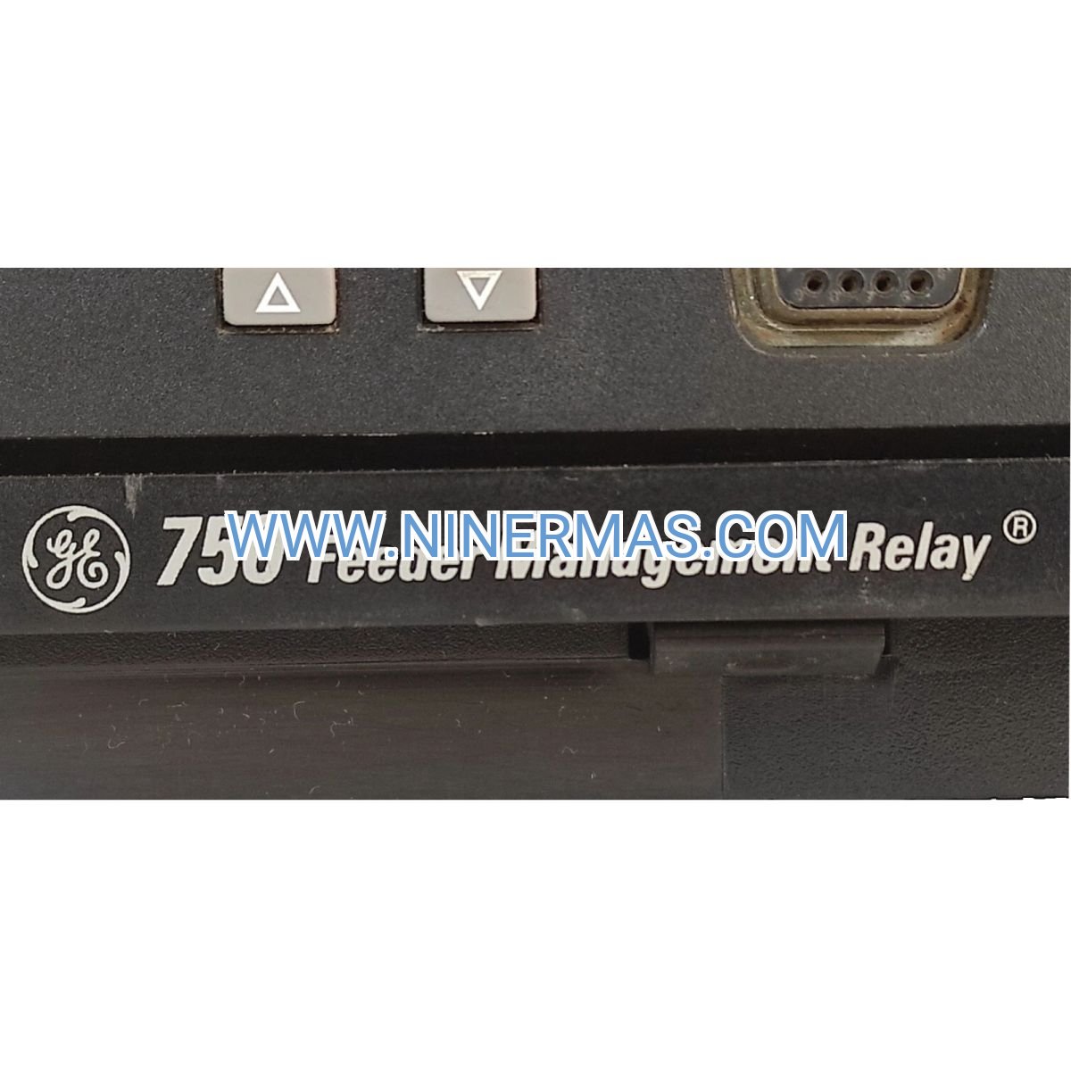
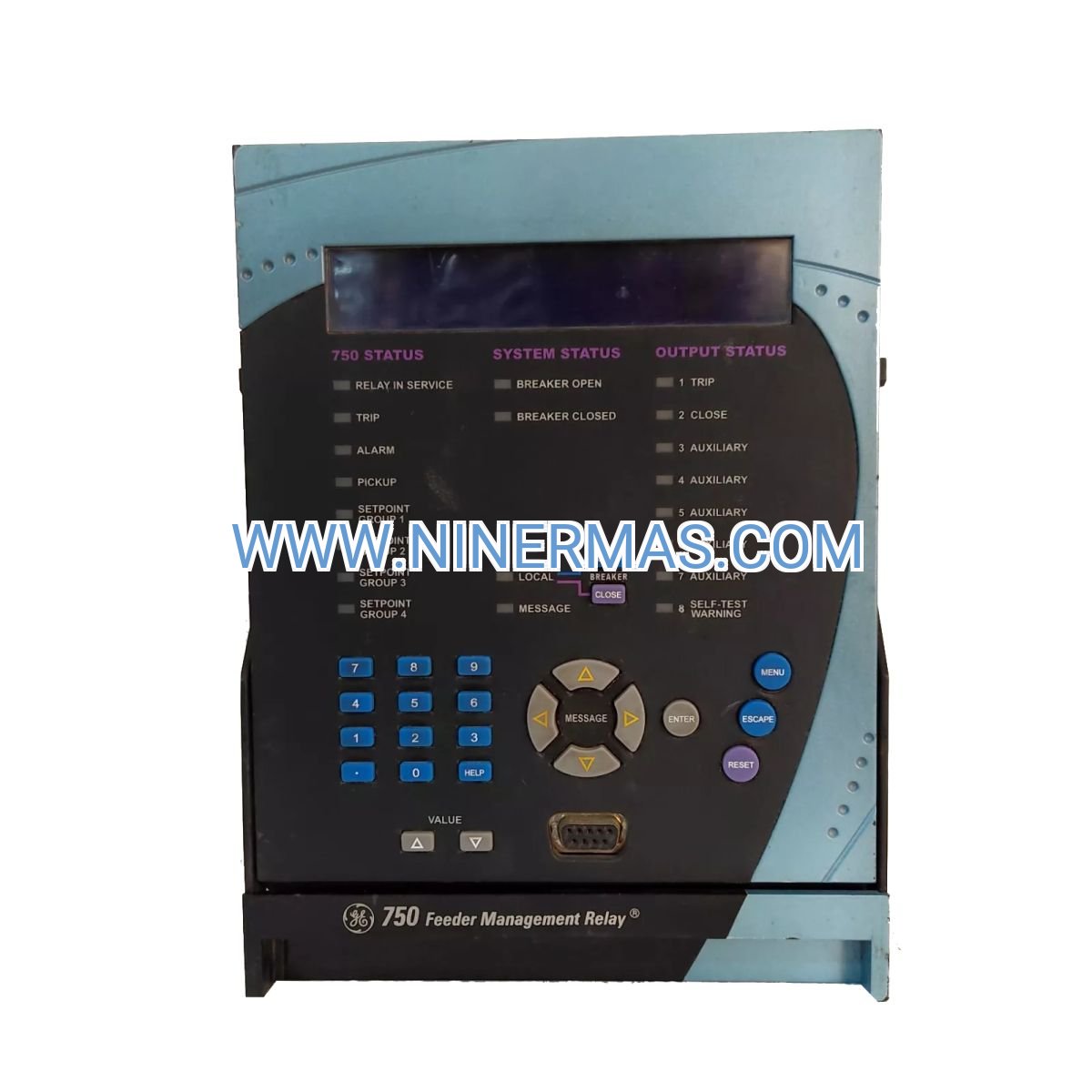
GE 750 Feeder Management Relay (Industrial-Grade Distribution Protection System)
The GE Multilin 750 Feeder Management Relay is an intelligent electronic device (IED) engineered for comprehensive protection, monitoring, and control of electrical distribution feeders in utility substations, industrial power networks, and renewable energy facilities. Through advanced overcurrent detection, precision metering, and programmable logic control, this relay delivers reliable safeguarding of medium-voltage feeders ranging from 4.16kV to 34.5kV class systems.
Designed for applications demanding continuous uptime and rapid fault isolation, the 750 relay addresses critical challenges including voltage fluctuations, ground fault detection delays, coordination complexity in looped networks, and limited visibility into feeder performance. It serves design engineers, system integrators, utility operators, and facility managers who require proven protection technology with flexible communication capabilities.
Built on GE's proven Multilin platform with standardized configurations and customizable I/O options, this relay offers fast-acting protection (operating times under 20ms), comprehensive event recording with 1ms resolution, multi-protocol communication support (Modbus RTU, DNP 3.0, IEC 61850), and intuitive local/remote configuration interfaces. Suitable for new installations, retrofit projects, and system expansions requiring coordinated protection schemes. Contact our application engineers for configuration recommendations and project-specific quotations.
Core Functions & Advantages
Comprehensive Overcurrent Protection
Integrates phase and ground time-overcurrent elements (ANSI 50/51, 50N/51N) with directional capability (67/67N), enabling selective fault isolation in radial and networked distribution systems. Programmable curves (IEC, IEEE, custom) ensure coordination with upstream breakers and downstream devices, minimizing nuisance trips while maintaining equipment safety margins.
Integrated Precision Metering
Real-time measurement of three-phase voltage, current, active/reactive power, energy consumption, power factor, and harmonic distortion provides operational visibility for load balancing, demand management, and predictive maintenance. Accuracy class 0.5S for revenue-grade applications meets utility billing requirements and regulatory compliance standards.
Advanced Fault Diagnostics
Sequence-of-events recording with millisecond timestamps, oscillography waveform capture (up to 64 cycles), and detailed fault reports accelerate root-cause analysis and reduce mean-time-to-repair. Automatic fault location estimation assists field crews in identifying cable faults and equipment failures, cutting outage duration by 40-60% compared to manual troubleshooting methods.
Flexible Communication Architecture
Dual serial ports plus optional Ethernet connectivity support simultaneous local HMI access and remote SCADA integration. Native protocol support (Modbus RTU, DNP 3.0, IEC 61850) eliminates gateway requirements, reducing system complexity and points of failure. Cybersecurity features include role-based access control, encrypted communications, and comprehensive audit logging for critical infrastructure protection.
Programmable Logic & Control
Built-in logic engine with 128 virtual inputs/outputs enables custom control schemes including automatic transfer switching, load shedding, capacitor bank control, and interlocking sequences. Reduces external PLC requirements and simplifies panel design, lowering installation costs by 15-25% in typical substation automation projects.
Robust Environmental Performance
Operating temperature range of -40°C to +85°C with conformal coating protection ensures reliable operation in harsh industrial environments including outdoor substations, coastal facilities, and high-humidity process plants. ANSI/IEEE C37.90 compliance for surge withstand, electromagnetic compatibility, and seismic qualification meets utility-grade reliability standards.
Typical Application Scenarios
This relay addresses protection and monitoring requirements across diverse power distribution environments, particularly where system reliability, fault response speed, and operational data visibility are critical:
Utility Distribution Substations
Protects primary and secondary distribution feeders in municipal and rural electric cooperatives, providing coordinated overcurrent protection, voltage regulation monitoring, and SCADA integration for grid automation initiatives. Directional elements enable protection of looped and meshed network configurations, supporting advanced distribution management system (ADMS) deployments.
Industrial Manufacturing Facilities
Safeguards critical production feeders in automotive plants, semiconductor fabs, food processing facilities, and chemical manufacturing sites where unplanned outages result in significant production losses. Fast ground fault detection (under 50ms) protects expensive process equipment and prevents arc flash incidents, while integrated metering supports ISO 50001 energy management compliance.
Commercial & Institutional Campuses
Monitors and controls distribution feeders in hospitals, universities, data centers, and large commercial complexes requiring high availability and power quality. Voltage and frequency protection elements detect utility supply anomalies, triggering automatic transfer to backup generation systems and preventing sensitive equipment damage from voltage sags or swells.
Renewable Energy Installations
Provides IEEE 1547-compliant protection for solar photovoltaic arrays and wind turbine collector systems, ensuring safe grid interconnection and rapid islanding detection. Works in coordination with generator protection relays to maintain power quality during variable generation conditions and support utility interconnection requirements for distributed energy resources.
Water & Wastewater Treatment Plants
Protects pump station feeders and treatment process distribution systems where continuous operation is essential for public health and environmental compliance. Integrates with SCADA systems for remote monitoring of pump performance, energy consumption trending, and predictive maintenance scheduling based on operational analytics.
Technical Parameters & Selection Guide
To facilitate engineering design and equipment specification, we provide standardized configuration options with customization available for project-specific requirements:
| Parameter | Specification |
|---|---|
| Model Designation | 750-P1-G1-D1-HI-A20-R |
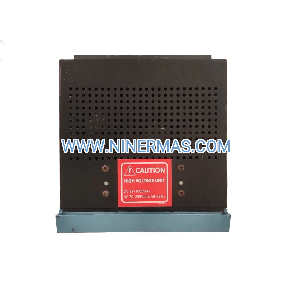
| Control Power Supply | 100-240V AC/DC (universal input), 20-48V DC optional |
| Current Transformer Inputs | 1A or 5A nominal (P1 configuration), 0.02-46A continuous |
| Voltage Transformer Inputs | Phase-phase: 300V AC nominal; Phase-neutral: 173V AC nominal |
| System Frequency | 50/60 Hz ±10% (45-66 Hz operating range) |
| Protection Functions | 50/51, 50N/51N, 67/67N, 27/59, 81O/81U, 79, 25 |
| Digital Inputs | 8 configurable (D1 option), 24-250V DC/AC |
| Output Relays | 6 Form-A contacts, 7A continuous @ 250V AC/DC |
| Communication Ports | 2× RS485 (rear), 1× RS232 (front), Ethernet optional (A20) |
| Protocols Supported | Modbus RTU, DNP 3.0, IEC 61850 (with A20 option) |
| Display Interface | 40-character backlit LCD with keypad (HI option) |
| Event Recording | 512 events with 1ms resolution, 8 oscillography records |
| Operating Temperature | -40°C to +85°C (-40°F to +185°F) |
| Enclosure Rating | NEMA 1 (panel mount), IP20 front / IP10 rear |
| Mounting Dimensions | 1/2 rack width: 96mm (W) × 165mm (H) × 220mm (D) |
| Compliance Standards | IEC 60255, IEEE C37.90, UL/cUL Listed |
Selection Considerations
When specifying the GE 750 relay for your application, consider the following system parameters: maximum and minimum load current levels, CT primary/secondary ratios, VT configuration (wye or delta), required protection functions (directional vs. non-directional), communication protocol requirements, available panel space, and control power voltage. For complex applications involving multiple feeders, looped networks, or integration with existing SCADA systems, our application engineers can review single-line diagrams and provide coordinated protection studies to ensure optimal relay settings and system selectivity.
Configuration Options Explained
The model code 750-P1-G1-D1-HI-A20-R indicates: P1 (CT input configuration), G1 (output relay configuration), D1 (8 digital inputs), HI (enhanced display with keypad), A20 (advanced communications with Ethernet/IEC 61850), R (rear communication ports). Alternative configurations are available for different I/O requirements, communication needs, and mounting preferences—consult factory documentation or contact technical support for configuration matrix details.
Extended Capabilities & System Integration
Substation Automation Integration
The 750 relay serves as a key component in IEC 61850-based substation automation architectures, supporting GOOSE messaging for high-speed peer-to-peer communication between protection devices. This enables advanced schemes including breaker failure protection, bus transfer automation, and distributed arc flash detection without requiring hardwired interlocking circuits, reducing installation costs and improving system flexibility for future modifications.
Cybersecurity & Access Control
Multi-level password protection with configurable user roles (view-only, operator, engineer, administrator) prevents unauthorized configuration changes and ensures audit trail compliance for NERC CIP and IEC 62351 requirements. Secure communication options including TLS encryption and certificate-based authentication protect against cyber threats in networked substation environments.
Predictive Maintenance Analytics
Continuous monitoring of breaker operation counters, contact wear indicators, and trip coil supervision data enables condition-based maintenance scheduling. Historical trending of load profiles, power factor, and harmonic content identifies developing issues such as insulation degradation, unbalanced loading, or capacitor bank failures before they result in unplanned outages.
Energy Management & Demand Response
Integrated energy metering with time-of-use registers and demand tracking supports utility rate optimization and demand response program participation. Programmable load shedding sequences can automatically reduce non-critical loads during peak demand periods, avoiding costly demand charges and supporting grid stability during supply constraints.
Delivery, Service & Quality Assurance
Lead Times & Availability
Standard catalog configurations (including the 750-P1-G1-D1-HI-A20-R model) typically ship within 2-4 weeks from order confirmation, subject to current production schedules. Custom-configured units with specialized I/O arrangements, alternative voltage ratings, or extended temperature options require 6-8 weeks for factory assembly and testing. Expedited delivery may be available for critical outage restoration or emergency replacement situations—contact our sales team for current availability and expedite options.
Warranty & Technical Support
All GE Multilin 750 relays include a comprehensive 24-month manufacturer warranty covering defects in materials and workmanship under normal operating conditions. Extended warranty programs and advance replacement services are available for critical infrastructure applications. Our technical support team provides application engineering assistance during project design, commissioning support including on-site startup services (available in select regions), and lifetime troubleshooting guidance via phone and email channels.
Documentation & Training Resources
Each relay ships with complete technical documentation including installation instructions, wiring diagrams, protection function descriptions, communication protocol implementation guides, and quick-start configuration templates. Comprehensive user manuals, application notes, and setting calculation spreadsheets are available for download from the GE Grid Solutions support portal. On-site and virtual training courses covering relay operation, advanced protection schemes, and communication system integration are offered through GE's global training network.
Compliance & Certifications
The 750 relay meets international standards for protective relay performance (IEC 60255 series), electromagnetic compatibility (IEC 61000 series), and safety (UL 508, CSA C22.2). Type testing per IEEE C37.90 includes dielectric withstand, surge immunity, electrostatic discharge, and seismic qualification. CE marking for European markets and RoHS compliance for hazardous substance restrictions ensure global applicability and regulatory acceptance.
Frequently Asked Questions (FAQ)
Q: How does the GE 750 Feeder Management Relay integrate with existing SCADA systems?
A: The relay supports industry-standard protocols including Modbus RTU (serial) and DNP 3.0 (serial or Ethernet with A20 option), enabling direct connection to most SCADA master stations without protocol converters. Communication mapping includes all metered values, protection status points, alarm conditions, and control commands. For IEC 61850 integration, the A20 communication option provides full MMS client/server functionality and GOOSE messaging capability. Configuration files (ICD/CID) are generated using the relay's configuration software for seamless integration into substation automation systems.
Q: What is the maximum number of feeders that can be protected with a single 750 relay?
A: Each 750 relay is designed to protect one three-phase feeder circuit. For multi-feeder applications, multiple relays are deployed with coordinated settings to ensure selective fault isolation. The relay's communication capabilities allow centralized monitoring and control of multiple units through a single SCADA interface, simplifying operations in substations with numerous feeder circuits. Panel space requirements are minimized through the compact 1/2 rack width design, allowing up to 8 relays in a standard 19-inch rack enclosure.
Q: Can the GE 750 relay be retrofitted into panels originally designed for electromechanical relays?
A: Yes, the 750's compact dimensions and flexible mounting options make it well-suited for retrofit applications. The relay's universal control power input (100-240V AC/DC) accommodates various existing control power systems without requiring additional power supplies. CT and VT connections are compatible with standard instrument transformer secondaries (1A or 5A current, 120V or 69V voltage). Output relay contacts can directly replace electromechanical relay contacts for breaker trip and alarm functions. Retrofit projects typically achieve 30-50% panel space savings compared to equivalent electromechanical protection schemes.
Q: What protection coordination tools are available for setting the 750 relay?
A: GE provides the EnerVista 750 Setup software (free download) for relay configuration, setting calculation, and event analysis. The software includes built-in time-current curve plotting for coordination studies with upstream and downstream protective devices. For comprehensive system-wide coordination analysis, the relay settings can be exported to third-party protection coordination software packages (SKM PowerTools, ETAP, ASPEN) via standard file formats. Our application engineering team can also perform coordination studies as part of project support services.
Q: How does the relay handle current transformer saturation during high-magnitude fault conditions?
A: The 750 employs advanced digital signal processing algorithms that detect and compensate for CT saturation effects, maintaining protection accuracy even when CT secondary current waveforms are distorted. The relay's wide dynamic range (0.02A to 46A continuous, 100A for 1 second) accommodates both light load conditions and severe fault currents without requiring CT tap changes. For applications with extremely high fault current levels (>100× rated current), consult our application engineers regarding CT selection and relay settings to ensure optimal performance under all operating conditions.
Q: What cybersecurity measures are implemented in the 750 relay for critical infrastructure protection?
A: The relay includes multiple layers of cybersecurity protection: role-based access control with individual user accounts and password policies, comprehensive event logging of all configuration changes and access attempts, optional communication encryption for Ethernet connections (with A20 option), and front panel lockout to prevent unauthorized local access. For compliance with NERC CIP standards or IEC 62351 requirements, the relay can be deployed behind network security appliances (firewalls, intrusion detection systems) with communication restricted to authorized SCADA master stations. Regular firmware updates address emerging security vulnerabilities and maintain compliance with evolving cybersecurity standards.
Q: Is the GE 750 relay suitable for arc flash reduction applications?
A: While the 750 provides fast-acting overcurrent protection that can reduce arc flash incident energy by minimizing fault clearing times, it does not include dedicated arc flash detection sensors. For comprehensive arc flash mitigation in low-voltage and medium-voltage switchgear, consider integrating the 750 with dedicated arc flash relay systems or light-sensing arc detection devices. The relay's high-speed communication capabilities (GOOSE messaging with A20 option) enable coordination with arc flash systems for rapid breaker tripping and zone-selective interlocking schemes that limit arc flash exposure to the faulted equipment only.
Request Technical Consultation & Quotation
To receive detailed application recommendations, protection coordination analysis, or project-specific pricing for the GE 750 Feeder Management Relay, please provide the following information to our engineering team:
- Project name and application type (utility substation, industrial facility, renewable energy, etc.)
- System voltage class and feeder configuration (radial, looped, networked)
- Current transformer ratios and voltage transformer configurations
- Required protection functions and coordination requirements
- Communication protocol and SCADA integration needs
- Control power voltage available at installation site
- Environmental conditions (indoor/outdoor, temperature range, altitude)
- Quantity required and desired delivery schedule
Our application engineers will review your requirements and provide customized recommendations including relay configuration selection, preliminary settings calculations, panel layout suggestions, and comprehensive quotations. For ongoing projects requiring multiple protection devices, we offer coordinated system design services to ensure optimal protection performance and regulatory compliance.
© 2026 NINERMAS COMPANY LIMITED. All rights reserved.
Original Source: https://ninermas.com
Contact: sale@ninermas.com | +0086 187 5021 5667


Contact Info
-
Address:22 / F, South Wo Hang building, 148 Wing Lok Street, Sheung Wan, Western District, Hong Kong
-
Phone:+8618750215667
-
Email: