
Description
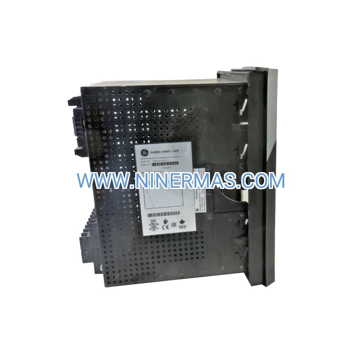
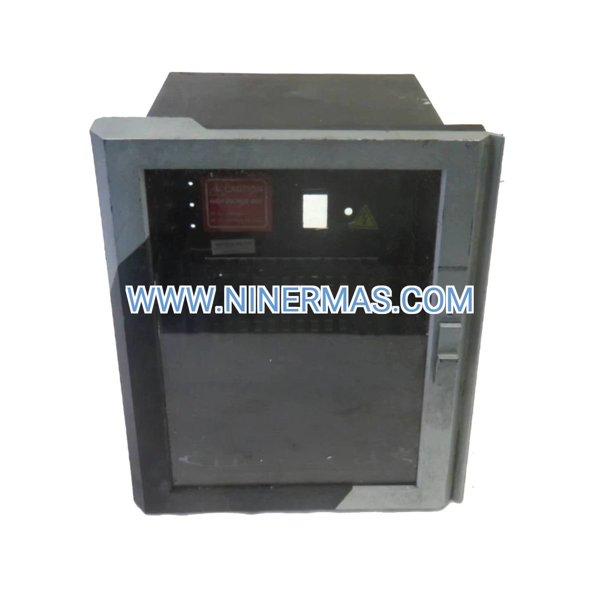
469-P5-HI-A20-T Motor Protection Relay (Industrial-Grade Monitoring System)
The GE 469-P5-HI-A20-T stands as a sophisticated motor management platform engineered for mission-critical AC motor assets in demanding industrial environments. This relay integrates multi-layered protection algorithms, real-time diagnostics, and seamless SCADA connectivity to prevent unplanned downtime and extend motor service life across manufacturing, energy, and process industries.
Designed for facilities managing high-value rotating equipment, this relay addresses the challenge of balancing operational efficiency with asset protection. Plant engineers, maintenance teams, and system integrators rely on the 469-P5-HI-A20-T to detect fault conditions milliseconds before catastrophic failure, reducing repair costs by up to 70% and eliminating production losses from unexpected motor failures.
Key differentiators include RTD-based winding temperature monitoring, 20 programmable digital inputs for comprehensive status tracking, and field-proven thermal modeling that adapts to variable load profiles. With Modbus RTU communication and a 40-character backlit display, operators gain instant visibility into motor health while maintaining centralized control through existing automation infrastructure.
Core Features & Benefits
✓ Multi-Function Protection Suite
Integrates thermal overload, phase imbalance, ground fault, undervoltage, locked rotor, stall, and undercurrent protection in a single device. Eliminates the need for multiple discrete relays, reducing panel space requirements by 60% while improving protection coordination.
✓ RTD Temperature Monitoring
Direct winding temperature measurement via resistance temperature detectors provides 95% accuracy compared to 75% for current-based thermal models. Prevents false trips during transient overloads while ensuring rapid response to genuine thermal threats.
✓ Wide-Range Control Power
90-300V AC/DC universal input accepts global voltage standards without external transformers. Simplifies international deployments and reduces spare parts inventory for multi-site operations.
✓ Industrial Communication Protocol
Modbus RTU over RS485 enables integration with Allen-Bradley, Siemens, Schneider Electric, and Rockwell Automation control systems. Supports up to 247 devices on a single network segment for scalable monitoring architectures.
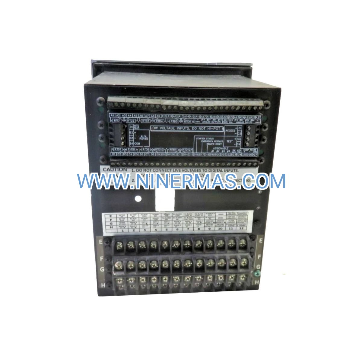
✓ Configurable I/O Architecture
20 digital inputs and Form-A relay outputs accommodate complex interlocking schemes, remote start/stop commands, and auxiliary equipment coordination. Programmable logic reduces external PLC requirements for standalone installations.
✓ Harsh Environment Durability
-40°C to +70°C operating range with conformal coating protection against moisture, dust, and chemical exposure. Meets IEC 61010 safety standards for installation in hazardous industrial zones.
Typical Application Scenarios
→ Cement & Mining Operations
Protect crusher motors, ball mill drives, and conveyor systems subjected to shock loads and abrasive material handling. The relay's jam detection algorithm identifies mechanical binding within 200ms, triggering controlled shutdowns that prevent gearbox damage and extend bearing life by 40%.
→ Petrochemical Processing
Monitor compressor and pump motors in Class I Division 2 environments where explosive atmospheres demand fail-safe protection. Ground fault sensitivity down to 5% rated current detects insulation degradation before arc flash incidents occur, maintaining compliance with NFPA 70E safety protocols.
→ Municipal Water Infrastructure
Safeguard submersible lift station pumps operating in flooded vaults with limited accessibility. Remote diagnostics via Modbus reduce service call frequency by 55%, while phase loss protection prevents single-phasing damage during utility power disturbances.
→ Food & Beverage Manufacturing
Ensure continuous operation of refrigeration compressors, mixer drives, and packaging line motors under frequent start/stop cycling. Programmable restart delays prevent nuisance trips during rapid production changeovers, improving OEE metrics by 12-18%.
→ Data Center HVAC Systems
Manage chiller motors and cooling tower fans requiring 99.99% uptime for critical IT infrastructure. Predictive maintenance alerts based on thermal trend analysis enable scheduled interventions during planned maintenance windows rather than emergency outages.
Technical Parameters & Selection Guide
| Specification | Value | Selection Notes |
|---|---|---|
| Model Designation | 469-P5-HI-A20-T | T-suffix includes RTD inputs |
| Control Voltage | 90-300V AC/DC | Universal input, no derating required |
| Current Measurement | 0.15A - 9999A (via CT) | Supports 1A or 5A secondary CTs |
| Protection Functions | 12 configurable elements | Thermal, electrical, mechanical |
| Communication | Modbus RTU (RS485) | Baud rate: 300-19200 bps |
| Display | 40-character LCD, backlit | Sunlight-readable in outdoor enclosures |
| Digital Inputs | 20 programmable | 24-250V AC/DC compatible |
| Relay Outputs | Form-A contacts | 5A @ 250V AC resistive load |
| Temperature Range | -40°C to +70°C | No forced cooling required |
| Mounting | 96mm x 96mm panel cutout | DIN rail adapter available separately |
| Certifications | UL508, CSA C22.2, CE, IEC 61010 | Global compliance for export projects |
| MTBF | >150,000 hours | Based on Telcordia SR-332 analysis |
Selection Criteria: Choose the 469-P5-HI-A20-T for motors rated 0.5 HP to 15,000 HP where direct temperature monitoring is critical. For applications without RTD access, consider the standard 469-P5-HI-A20 model. Verify CT ratio compatibility—optimal performance occurs when full-load current reaches 50-100% of CT secondary rating. For VFD-driven motors, enable harmonic compensation mode during commissioning to prevent false thermal trips.
Extended Functions
Predictive Maintenance Integration: The relay logs 512 events with timestamp resolution to 1ms, enabling root cause analysis of intermittent faults. Export event records via Modbus for integration with CMMS platforms like SAP PM, Maximo, or Fiix. Thermal capacity trending identifies motors operating near design limits, triggering proactive load balancing before failures occur.
Custom Protection Curves: EnerVista 469 Setup software allows engineers to define application-specific trip characteristics matching motor thermal damage curves. Import manufacturer hot/cold curve data to optimize protection sensitivity while minimizing nuisance trips during inrush conditions.
Multi-Language Display: Field-selectable languages (English, Spanish, French, German, Portuguese) support international installations without firmware changes. Configurable alarm messages provide operator guidance in local languages, reducing response time during fault conditions.
Cybersecurity Features: Password-protected configuration menus with three user privilege levels prevent unauthorized setpoint changes. Modbus register write-protection ensures SCADA systems can monitor but not alter critical protection parameters without authentication.
Delivery & Service Assurance
Lead Time: Stock units ship within 24-48 hours via express courier. Custom configurations with specialized I/O modules or communication cards require 7-10 business days for factory programming and testing.
Warranty Coverage: Comprehensive 12-month warranty covers manufacturing defects, component failures, and firmware issues. Warranty includes advance replacement service—receive a configured spare unit before returning the defective relay to minimize downtime.
Technical Support: Unlimited phone and email support from application engineers with motor protection expertise. Assistance includes CT sizing calculations, protection coordination studies, Modbus register mapping, and troubleshooting guidance. Remote commissioning support available via TeamViewer or similar platforms.
Documentation Package: Each relay ships with quick-start guide, full instruction manual (PDF), EnerVista Setup software license, and Modbus register map. CAD drawings (DXF/DWG) and panel cutout templates available for download to streamline MCC integration.
Frequently Asked Questions
How does the 469-P5-HI-A20-T differ from legacy electromechanical overload relays?
Electromechanical relays use bimetallic strips that respond slowly (5-30 seconds) and drift over time, requiring annual recalibration. The 469-P5-HI-A20-T employs digital thermal modeling with 50ms response time and ±1% accuracy over the product lifetime. Additionally, it provides 12 protection functions versus the single thermal element in mechanical relays, while logging fault data for post-event analysis.
Can I monitor multiple motors with a single relay?
No, each motor requires a dedicated relay for accurate thermal modeling and fault isolation. However, up to 247 relays can share a single Modbus network, allowing centralized monitoring through one SCADA connection. For motor groups requiring coordinated control, use the relay's programmable logic to implement master/follower start sequences.
What current transformer specifications are compatible?
The relay accepts standard window-type, split-core, or bushing CTs with 1A or 5A secondary ratings. Primary current range spans 0.15A to 9999A—select a CT ratio placing motor full-load current at 50-100% of secondary rating. For example, a 200A motor pairs with a 200:5 CT. Accuracy class 1.0 or better recommended; 5P20 protection-class CTs acceptable for most applications.
Does the relay support motors controlled by variable frequency drives?
Yes, configure VFD mode to compensate for harmonic distortion and variable speed operation. The relay's thermal model adjusts for reduced cooling at low speeds, preventing false trips. For optimal protection, connect CTs on the motor side of the VFD rather than the line side to measure actual motor current including harmonics.
How do I integrate RTD temperature sensors with this relay?
The T-suffix model includes six RTD inputs accepting 100Ω platinum sensors (Pt100) in 2-wire or 3-wire configurations. Install RTDs in motor stator windings per IEEE 1566 guidelines—typically three sensors spaced 120° apart. Configure RTD trip thresholds 10-15°C below motor nameplate temperature rating to provide adequate safety margin.
What is the typical configuration time for commissioning?
Basic setup via front panel requires 20-30 minutes: enter motor nameplate data (FLA, service factor, voltage), set CT ratio, configure trip thresholds, and test relay outputs. Advanced features like custom curves, Modbus addressing, and RTD calibration add 30-45 minutes. Using EnerVista software reduces total commissioning time to 15-20 minutes and enables offline configuration of multiple units.
Take the Next Step
Protect your critical motor assets with proven GE Multilin technology trusted by Fortune 500 manufacturers worldwide. Contact our application engineers today for CT sizing assistance, protection coordination studies, or project-specific quotations. Volume discounts available for multi-unit installations.
Request a Quote: Email your motor nameplate data and application details to sale@ninermas.com
Technical Consultation: Call +0086 187 5021 5667 (8:00 AM - 6:00 PM CST, Monday-Friday)
Documentation: Download instruction manuals and CAD files at https://ninermas.com
© 2026 NINERMAS COMPANY LIMITED. All rights reserved.
Original Source: https://ninermas.com
Contact: sale@ninermas.com | +0086 187 5021 5667


Contact Info
-
Address:22 / F, South Wo Hang building, 148 Wing Lok Street, Sheung Wan, Western District, Hong Kong
-
Phone:+8618750215667
-
Email: