Description
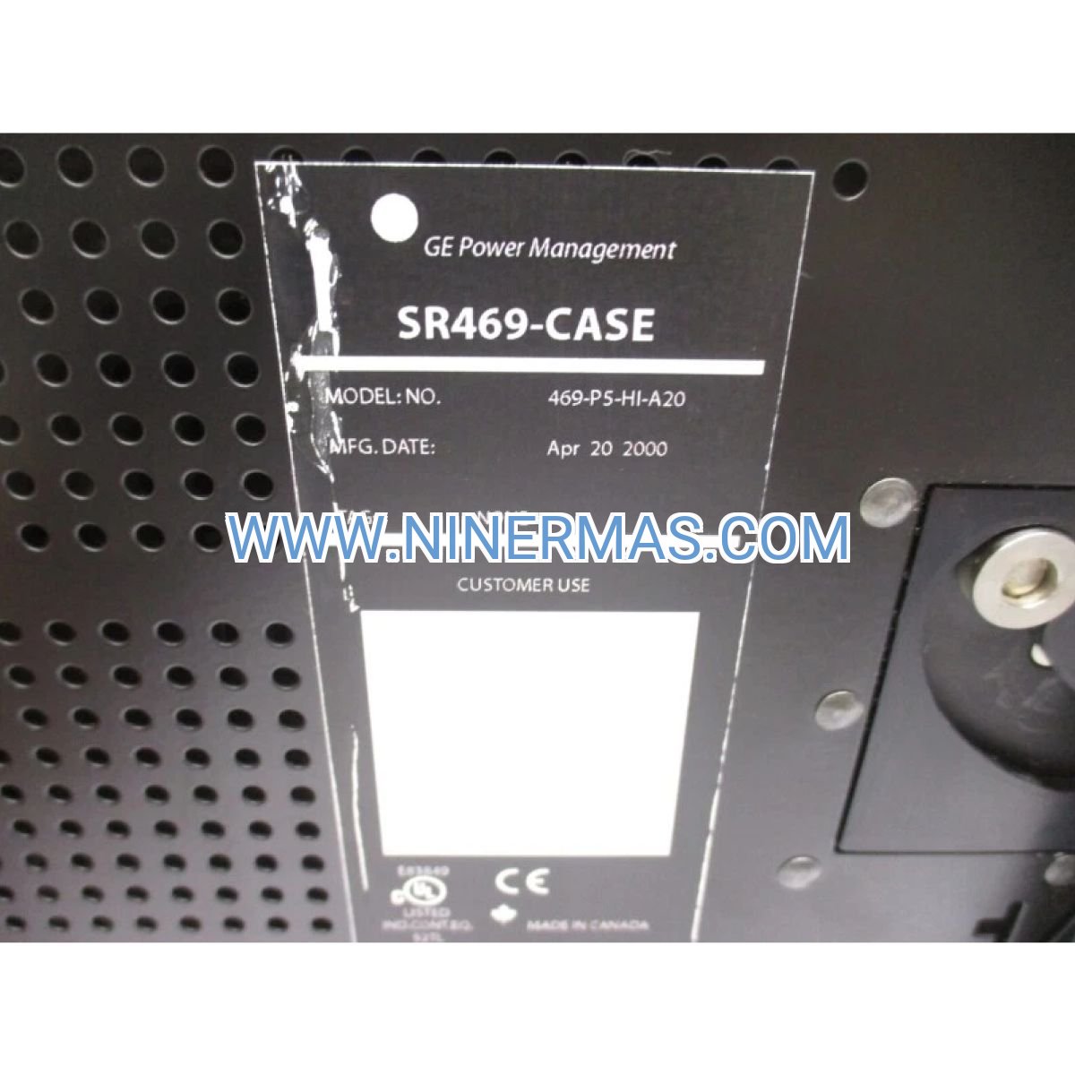
GE Multilin 469-P5-HI-A20 Motor Protection Relay (Industrial-Grade Motor Management System)
The GE Multilin 469-P5-HI-A20 is a microprocessor-based motor protection relay engineered for comprehensive protection, control, and real-time monitoring of medium to large horsepower motors in industrial environments. Through advanced thermal modeling algorithms, multi-protocol communication interfaces (Modbus RTU), and intelligent diagnostic capabilities, this relay delivers proactive motor health management, minimizes unplanned downtime, and extends equipment service life.
Designed for critical applications across manufacturing, process industries, water treatment facilities, and power generation plants, the 469-P5-HI-A20 addresses common challenges including thermal overload damage, mechanical jam detection failures, current unbalance issues, and inadequate ground fault protection. It provides plant engineers, maintenance teams, and system integrators with actionable insights through continuous metering of voltage, current, power, frequency, demand, energy consumption, motor load percentage, and remaining thermal capacity.
Built on GE's proven Multilin platform with field-tested reliability, this motor management relay features standardized configuration templates and flexible customization options. Key advantages include adaptive thermal protection curves, multi-channel RTD temperature monitoring, event logging with timestamp precision, four isolated 4-20 mA analog outputs for SCADA integration, and six programmable output relays for trip/alarm coordination. Suitable for design consultants, panel builders, OEM equipment manufacturers, and end-user facility operators seeking UL/CSA certified motor protection solutions. Contact our application engineers for motor-specific protection coordination studies and relay configuration assistance.
Core Functions & Advantages
Adaptive Thermal Overload Protection
Utilizes patented thermal modeling algorithms that continuously calculate motor winding temperature based on load current, ambient conditions, and cooling efficiency. Prevents insulation degradation and winding burnout while allowing safe short-term overload operation during startup transients, reducing nuisance trips by up to 40% compared to conventional bimetallic overloads.
Comprehensive Multi-Function Protection Suite
Integrates 15+ protection elements in a single device: thermal overload (RTD-biased), locked rotor/jam detection, current unbalance (phase loss), ground fault (dual CT inputs), undervoltage/overvoltage, underpower, phase reversal, and stator differential protection. Eliminates the need for multiple discrete relays, reducing panel space requirements and wiring complexity by approximately 60%.
Advanced Diagnostic & Predictive Maintenance
Continuously monitors motor operating parameters including starts per hour, running hours, thermal capacity used, bearing temperature trends (via RTD inputs), and vibration signatures (when interfaced with external sensors). Provides early warning of developing faults through programmable alarm thresholds, enabling condition-based maintenance scheduling and preventing catastrophic failures.
Multi-Protocol Industrial Communication
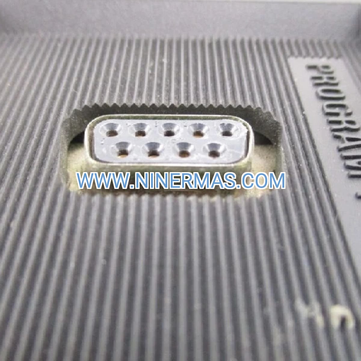
Equipped with one front-panel RS232 port and two rear RS485 ports supporting Modbus RTU protocol for seamless integration with DCS, SCADA, and plant-wide monitoring systems. Enables remote setpoint adjustment, real-time data acquisition at 1-second intervals, and centralized alarm management across distributed motor assets, reducing site visit requirements for routine monitoring.
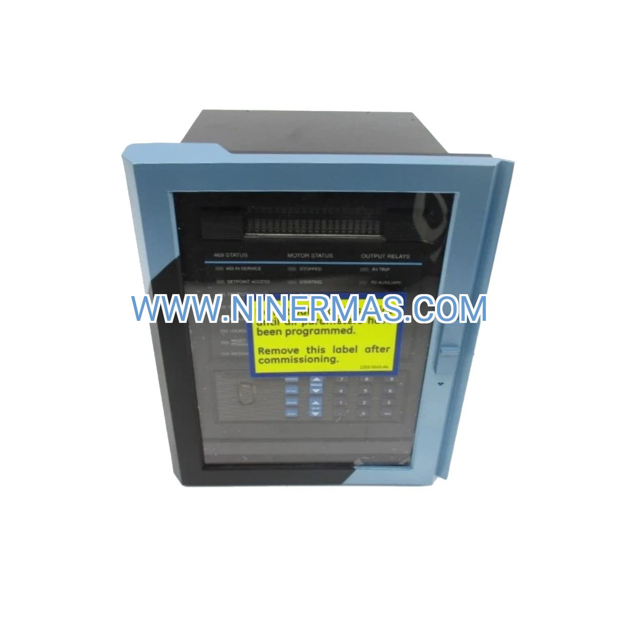
Intuitive Local Interface & Event Recording
Features a backlit 40-character LCD display with multi-language support and membrane keypad for on-site configuration and troubleshooting. Automatically logs the last 256 events with precise timestamp, fault cause identification, and pre-fault operating conditions (current, voltage, load %), facilitating rapid root cause analysis and reducing mean time to repair (MTTR) by an average of 35%.
Flexible Analog Output Integration
Provides four independently configurable 4-20 mA analog outputs that can transmit any monitored parameter (motor current, power, temperature, load %, thermal capacity) to external recorders, PLCs, or building management systems. Supports legacy control systems without requiring protocol converters, ensuring compatibility with existing plant infrastructure.
Typical Application Scenarios
This motor protection relay is engineered for applications demanding high reliability, continuous operation, and comprehensive motor health visibility, particularly in:
Process Industry Critical Pumps & Compressors
Protects high-value motors driving centrifugal pumps, screw compressors, and rotary blowers in chemical processing, oil & gas refining, and pharmaceutical manufacturing. Prevents costly process interruptions caused by motor failures, with thermal modeling accuracy validated for motors ranging from 50 HP to 5000 HP. Supports both NEMA and IEC motor standards.
Water & Wastewater Treatment Facilities
Ideal for municipal water pumping stations, wastewater lift stations, and industrial cooling water systems requiring 24/7 operation. Ground fault protection with dual CT inputs detects insulation breakdown in wet environments, while RTD-biased thermal protection compensates for variable ambient temperatures in outdoor installations. Complies with EPA reliability requirements for critical infrastructure.
Manufacturing Production Line Motors
Ensures uptime for conveyor drives, mixer motors, extruder drives, and machine tool spindles in automotive, food processing, and packaging industries. Locked rotor detection with adjustable time delays prevents mechanical damage during jam conditions, while current unbalance protection identifies single-phasing events before motor damage occurs. Reduces production line downtime costs averaging $5,000-$50,000 per hour.
HVAC & Building Systems
Manages chiller motors, cooling tower fans, and air handling unit drives in commercial buildings, data centers, and hospital facilities. Integrates with BACnet or Modbus-based building automation systems via analog outputs and serial communication, providing facility managers with centralized motor performance dashboards. Energy metering functions support LEED certification and utility demand response programs.
Power Generation & Utility Applications
Protects auxiliary motors in power plants including boiler feed pumps, induced draft fans, and coal pulverizers. Meets IEEE and ANSI protection coordination standards, with adjustable time-current curves for selective coordination with upstream circuit breakers. Event recording capabilities satisfy regulatory compliance requirements for critical infrastructure documentation.
Technical Parameters & Selection Guide
To facilitate engineering design and product selection, we provide standardized configuration options with customization available for project-specific requirements:
| Parameter Category | Specification Details |
|---|---|
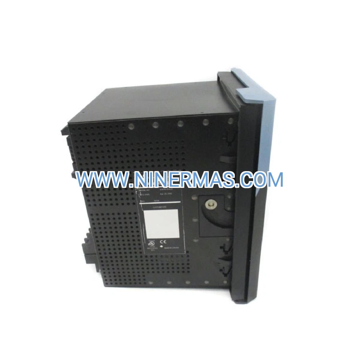
| Model Designation | 469-P5-HI-A20 (5A CT secondary, High voltage input, Four 4-20mA outputs) |
| Current Transformer Rating | 5 A secondary (P5 option) | Compatible with CT ratios from 50:5 to 6000:5 |
| Control Power Supply | 90-300 VDC or 70-265 VAC, 48-62 Hz (HI option) | Universal input for global applications |
| Voltage Transformer Inputs | Three-phase, supports delta or wye configuration | Rated 69-240 VAC line-to-neutral |
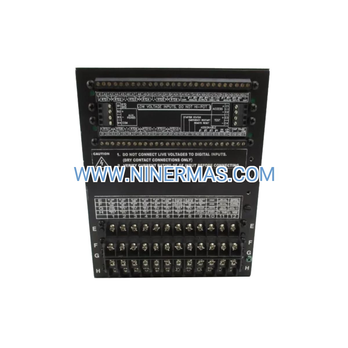
| RTD Temperature Inputs | Up to 12 channels | Supports 100Ω Pt, 120Ω Ni, 100Ω Ni, 10Ω Cu | 3-wire connection |
| Ground Fault Detection | Dual ground CT inputs | Sensitivity range: 2-800% of CT rating | Adjustable time delay: 0.05-600s |
| Output Relays | 6 Form-C contacts | Rating: 10A continuous, 30A make/carry for 0.2s | Programmable for trip/alarm/auxiliary |
| Analog Outputs | Four isolated 4-20 mA outputs (A20 option) | Accuracy: ±0.5% of full scale | Load resistance: 0-750Ω |
| Communication Interfaces | 1x RS232 (front panel) + 2x RS485 (rear terminals) | Modbus RTU protocol | Baud rate: 1200-19200 bps |
| Display & Interface | 40-character backlit LCD | 16-key membrane keypad | Multi-language menu system |
| Event & Data Recording | 256 event log entries with timestamp | 8 oscillography records | 16 demand log entries |
| Operating Temperature | -40°C to +60°C (-40°F to +140°F) | LCD functional above -20°C | Humidity: 5-95% non-condensing |
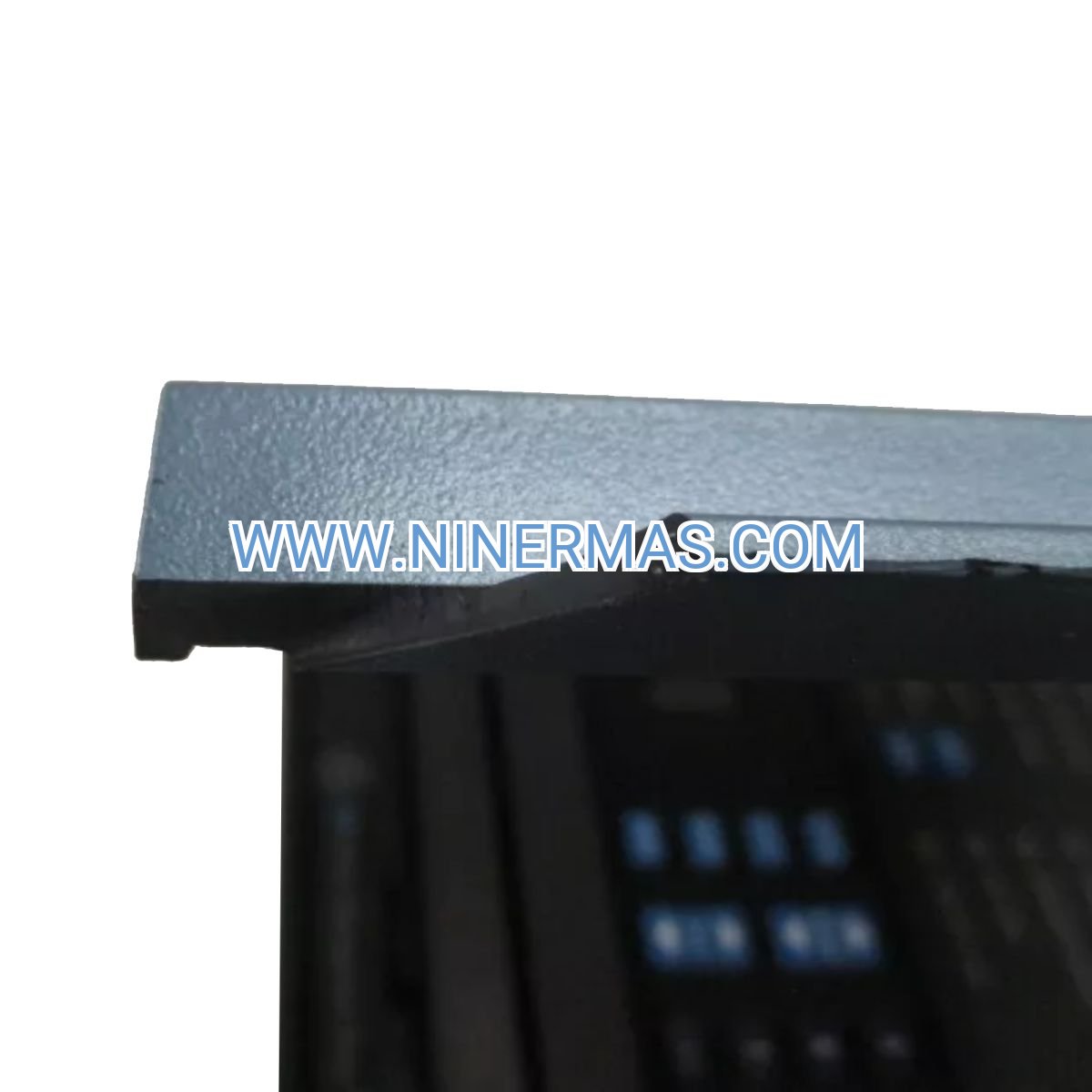
| Enclosure Protection | Front: IP40 (NEMA 1 equivalent) | Rear terminals: IP20 | Draw-out case design for hot-swap capability |
| Physical Dimensions | Case: 218mm (W) × 228mm (H) × 250mm (D) | Panel cutout: 203mm × 203mm | Depth behind panel: 225mm |
| Weight | 7.32 kg (16.14 lbs) with SR469 metal case | Suitable for standard 19" relay panels |
| Compliance & Certifications | UL 508 Listed | CSA C22.2 No. 14 | CE marked (LVD, EMC directives) | IEC 60255 protection relay standard |
| Configuration Software | EnerVista 469 Setup (Windows-based) | Supports offline configuration, data trending, waveform capture analysis |
Selection Recommendations:
When specifying this motor protection relay, consider the following application parameters: motor full-load current and service factor, existing CT ratios and accuracy class, available control power voltage, required temperature monitoring points (bearings, windings, ambient), SCADA system communication protocol requirements, and panel space constraints. For motors above 500 HP or applications requiring stator differential protection, consult with our protection coordination engineers to verify CT sizing and relay settings. Custom configurations available for non-standard voltage ratings, alternative communication protocols (DNP3, IEC 61850), and hazardous location certifications (Class I Div 2).
Extended Capabilities & Integration Options
SCADA & DCS Integration
Seamless connectivity to Wonderware, Rockwell FactoryTalk, Siemens WinCC, and Schneider Electric EcoStruxure platforms via Modbus RTU mapping. Pre-configured register maps available for common SCADA packages, reducing commissioning time by 50%. Supports both polling and exception-based reporting for bandwidth optimization.
Predictive Maintenance Analytics
When connected to GE's Asset Performance Management (APM) software or third-party condition monitoring systems, the relay's continuous data streams enable machine learning algorithms to predict bearing failures 2-4 weeks in advance, optimize maintenance intervals based on actual thermal stress accumulation, and benchmark motor efficiency across plant assets.
Energy Management & Reporting
Built-in energy metering functions (kWh, kVARh, power factor) with demand tracking support utility billing verification, ISO 50001 energy management compliance, and identification of inefficient motor operation. Analog outputs can drive local energy dashboards or feed building energy management systems for real-time visibility.
Cybersecurity Considerations
Serial communication ports support password protection and read-only access modes to prevent unauthorized setpoint changes. For installations requiring IEC 62443 industrial cybersecurity compliance, the relay can be deployed behind protocol gateways with firewall capabilities and encrypted communication tunnels.
Delivery, Service & Quality Assurance
Lead Time & Availability:
Standard 469-P5-HI-A20 configuration typically ships within 3-5 business days from regional distribution centers. Custom configurations with alternative CT ratings, special voltage options, or additional I/O modules require 2-3 weeks for factory assembly and testing. Expedited delivery available for critical outage situations with 24-hour emergency processing.
Warranty & Support:
All GE Multilin motor protection relays include a standard 2-year manufacturer warranty covering defects in materials and workmanship. Extended warranty programs available for up to 5 years. Technical support provided through GE's global service network with 24/7 hotline access for critical applications. On-site commissioning and startup assistance available in major industrial regions.
Documentation & Training:
Each relay ships with comprehensive technical documentation including: detailed instruction manual (300+ pages), quick start guide, electrical connection diagrams, Modbus register mapping tables, protection setting calculation worksheets, and AutoCAD panel cutout drawings. EnerVista configuration software includes context-sensitive help and tutorial videos. On-site or web-based training courses available for plant personnel covering relay operation, protection coordination, and troubleshooting procedures.
Quality Certifications:
Manufactured in ISO 9001:2015 certified facilities with 100% functional testing prior to shipment. Each unit undergoes automated test sequences verifying protection accuracy, communication integrity, and environmental performance. Traceability documentation provided for projects requiring material certifications or compliance with nuclear quality assurance programs (10CFR50 Appendix B).
Frequently Asked Questions (FAQ)
Q: How does the GE Multilin 469 motor protection relay integrate with existing motor control centers and switchgear?
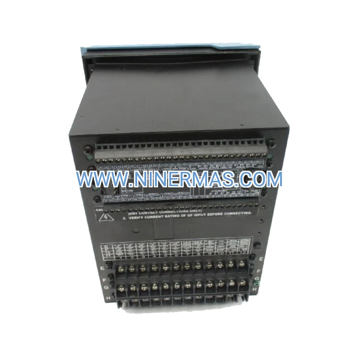
A: The 469-P5-HI-A20 utilizes a standard draw-out case design (SR469) that fits industry-standard relay panel cutouts (203mm × 203mm). It connects to existing current transformers (5A secondary), voltage transformers, and RTD sensors via rear screw terminals with clearly labeled connection points. The six output relays can directly interface with motor starter coils, annunciator panels, and PLC digital inputs. For retrofits, the relay often replaces 3-5 discrete protection devices (thermal overload, ground fault, undervoltage), simplifying panel wiring. Installation typically requires 4-6 hours for a qualified electrician including CT verification, setpoint programming, and functional testing.
Q: What is the maximum number of motors that one 469-P5-HI-A20 relay can protect simultaneously?
A: Each GE Multilin 469 relay is designed to protect a single three-phase motor. The relay's thermal model, protection algorithms, and metering functions are optimized for monitoring one motor's unique operating characteristics (nameplate data, thermal time constant, locked rotor current). For facilities with multiple motors, a dedicated relay is required for each critical motor asset. However, multiple 469 relays can be networked via RS485 Modbus communication to a single SCADA system for centralized monitoring, reducing the need for individual operator interfaces at each motor location.
Q: What energy savings can be achieved by implementing advanced motor protection with thermal modeling?
A: While the 469 relay itself is a protection device rather than an energy-saving controller, it enables energy optimization in several ways: (1) Prevents motor damage that leads to efficiency degradation—a motor that has experienced winding overheating can lose 2-5% efficiency permanently; (2) Provides real-time power and energy metering to identify motors operating at poor power factor or excessive no-load losses; (3) Supports integration with variable frequency drives (VFDs) by protecting the motor while the VFD optimizes speed for load conditions, typically achieving 20-40% energy reduction in variable-torque applications like pumps and fans; (4) Reduces unplanned downtime that forces operation of less-efficient backup equipment. Actual savings depend on motor size, duty cycle, and baseline protection adequacy.
Q: What are the environmental and installation requirements for reliable operation?
A: The 469-P5-HI-A20 is rated for industrial environments with operating temperatures from -40°C to +60°C, though the LCD display may have reduced contrast below -20°C (relay protection functions remain fully operational). The relay requires a control power supply within the 90-300 VDC or 70-265 VAC range with ±20% tolerance. Installation should be in a NEMA 1 or better enclosure to maintain the IP40 front panel rating. Avoid locations with excessive vibration (>2g acceleration), corrosive atmospheres (use conformal coating option if required), or strong electromagnetic interference near VFD output cables (maintain 300mm separation). Adequate ventilation is recommended to keep internal temperature below 50°C for maximum component lifespan. The relay does not require forced cooling or air conditioning in typical motor control room environments.
Q: Can the relay support remote monitoring and diagnostics over Ethernet or wireless networks?
A: The 469-P5-HI-A20 features native RS232 and RS485 serial communication ports with Modbus RTU protocol. For Ethernet connectivity, the relay can be connected to a Modbus RTU-to-Modbus TCP gateway (such as GE's MDS Gateway or equivalent third-party devices), enabling integration with Ethernet-based SCADA systems, cloud platforms, and mobile monitoring applications. For wireless connectivity in remote installations, serial-to-cellular modems or industrial Wi-Fi bridges can be deployed. GE also offers the 469-P5-HI-A20-E variant with embedded Ethernet port for direct network connection. Remote diagnostics capabilities include real-time parameter monitoring, event log retrieval, oscillography waveform download, and setpoint verification—all accessible through EnerVista software or custom SCADA interfaces without requiring site visits.
Q: How do I determine the correct protection settings and coordination with upstream circuit breakers?
A: Protection setting calculation requires motor nameplate data (HP/kW rating, voltage, full-load current, service factor, locked rotor current, thermal time constant) and system information (CT ratio, VT ratio, upstream breaker type and rating). GE provides detailed setting calculation worksheets in the instruction manual, and the EnerVista software includes a settings wizard that guides users through the process. For critical applications or complex coordination studies, we recommend engaging a protection engineering consultant or utilizing GE's application engineering services. Key coordination principles: (1) Thermal overload curve should be set at 105-115% of motor full-load current with time constant matching motor thermal characteristics; (2) Locked rotor protection typically set at 150-600% FLC with 2-10 second delay depending on motor starting time; (3) Ground fault protection coordinated to trip faster than upstream ground fault relays but slower than nuisance ground current transients. IEEE Standard 242 (Buff Book) provides comprehensive motor protection coordination guidelines.
Get Expert Selection Assistance
To ensure optimal motor protection system design and configuration for your specific application, please provide our application engineering team with the following project information: facility name and location, motor nameplate details (HP/kW, voltage, FLA, service factor, application description), existing or planned current transformer ratios, control power voltage availability, communication protocol requirements (Modbus RTU, DNP3, IEC 61850), temperature monitoring needs (number of RTDs, sensor types), and any special environmental conditions (hazardous area classification, extreme temperatures, high altitude). Our engineers will provide a detailed technical proposal including relay model selection, protection setting recommendations, panel layout drawings, and integration guidance within 2-3 business days.
© 2026 NINERMAS COMPANY LIMITED. All rights reserved.
Original Source: https://ninermas.com
Contact: sale@ninermas.com | +0086 187 5021 5667


Contact Info
-
Address:22 / F, South Wo Hang building, 148 Wing Lok Street, Sheung Wan, Western District, Hong Kong
-
Phone:+8618750215667
-
Email: