Description
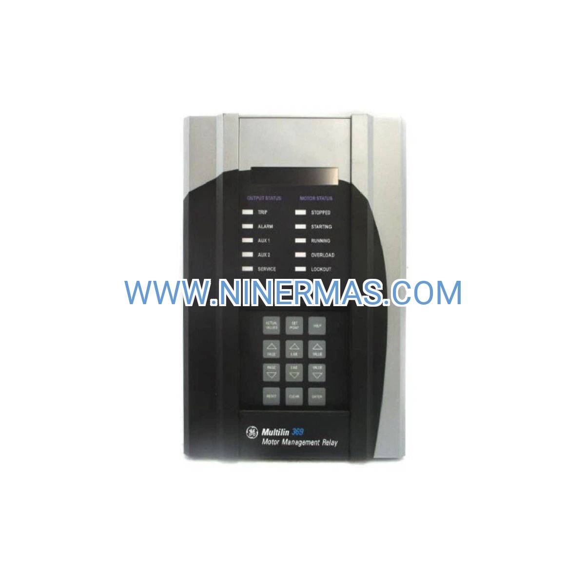
GE 369-HI-R-M-0-0-0-H-E Motor Protection Relay (Industrial-Grade Digital Motor Management System)
The GE 369-HI-R-M-0-0-0-H-E Motor Protection Relay is an industrial-grade digital protection and management device designed for AC motor applications across critical infrastructure and heavy industry. Through advanced microprocessor-based algorithms, integrated RTD temperature sensing, and real-time current monitoring, this relay delivers comprehensive motor protection, fault diagnostics, and predictive maintenance capabilities that minimize unplanned downtime and extend equipment service life.
Engineered for demanding environments including oil & gas facilities, water treatment plants, mining operations, and manufacturing complexes, the 369-HI-R-M-0-0-0-H-E addresses common motor failure modes such as thermal overload, phase imbalance, locked rotor conditions, bearing overheating, and supply voltage anomalies. The system supports motors ranging from 1 HP to over 10,000 HP, making it suitable for both auxiliary equipment and mission-critical prime movers.
Built on GE Multilin's three-decade legacy of protection relay innovation, this device combines field-proven reliability with modern communication protocols (Modbus RTU, RS485), intuitive configuration interfaces, and extensive event recording. Design engineers, system integrators, plant maintenance teams, and OEM equipment manufacturers can leverage standardized protection templates while retaining full customization flexibility for application-specific requirements. Contact our motor protection specialists for application-specific selection guidance, wiring diagrams, and competitive quotations.
Core Functions & Advantages
Precision Thermal Modeling with RTD Integration
Utilizes six independent RTD temperature inputs (100Ω/120Ω platinum) combined with current-based thermal algorithms to create an accurate thermal image of motor windings and bearings. This dual-layer approach prevents nuisance trips while ensuring protection against sustained overload conditions that electromechanical devices often miss. Real-time temperature trending enables condition-based maintenance scheduling.
Multi-Function Protection in Single Enclosure
Consolidates seven critical protection functions—thermal overload, phase current imbalance, ground fault detection, under/overvoltage monitoring, locked rotor protection, stall detection, and bearing temperature supervision—eliminating the need for multiple discrete devices. Reduces panel space requirements by up to 60% compared to traditional relay combinations while improving protection coordination.
Adaptive Protection for Variable Load Profiles
Configurable protection curves accommodate motors with frequent start/stop cycles, variable torque loads, or VFD-driven operation. The relay automatically adjusts thermal capacity calculations based on actual operating patterns, providing tighter protection margins without compromising operational flexibility. Compatible with soft starters and variable frequency drives from major manufacturers.
Comprehensive Fault Diagnostics & Event Recording
Captures detailed fault data including pre-fault current levels, temperature readings, voltage conditions, and time-stamped event sequences. The 40-character backlit LCD displays fault codes and operating parameters in plain language, accelerating troubleshooting and reducing mean time to repair (MTTR) by an average of 40% compared to indicator-light-only systems.
Industrial Communication & SCADA Integration
Standard Modbus RTU protocol over RS485 enables seamless integration with distributed control systems (DCS), programmable logic controllers (PLC), and supervisory control platforms. Remote monitoring of motor status, load current, operating hours, and alarm conditions supports centralized asset management and predictive maintenance programs across multi-site facilities.
Rugged Construction for Harsh Environments
IP20 front panel protection and wide operating temperature range (-40°C to +70°C) ensure reliable performance in dusty, high-vibration, and temperature-extreme locations. Conformal-coated circuit boards resist moisture and corrosive atmospheres common in chemical processing, wastewater treatment, and offshore installations. UL, CSA, CE, and IEC 61850 certifications validate compliance with international safety standards.
Typical Application Scenarios
This motor protection relay is engineered for installations where motor reliability directly impacts production continuity, safety systems, or environmental compliance. Representative applications include:
Municipal Water & Wastewater Infrastructure
Protects high-service pumps, lift station motors, aeration blowers, and clarifier drives in potable water distribution and sewage treatment facilities. The relay's resistance to humidity and temperature fluctuations makes it ideal for outdoor pump stations and below-grade installations. Prevents costly service interruptions that can trigger regulatory violations or emergency bypass operations.
Petroleum Refining & Petrochemical Processing
Safeguards compressor drives, pipeline pumps, cooling tower fans, and process circulation motors in Class I Division 2 environments. Advanced ground fault sensitivity detects insulation degradation before catastrophic failure, while bearing RTD monitoring prevents fire hazards from overheated equipment. Supports SIL-rated safety instrumented systems when properly configured.
Mining & Mineral Processing Operations
Ensures continuous operation of conveyor systems, SAG mills, crushers, flotation cells, and dewatering pumps in abrasive, high-shock environments. The relay withstands vibration levels exceeding 2g while maintaining protection accuracy. Event logging assists with failure analysis and warranty claim documentation for expensive mining equipment.
Manufacturing & Industrial Production Lines
Provides coordinated protection for material handling systems, HVAC equipment, machine tool drives, and process machinery in automotive, food & beverage, pharmaceutical, and general manufacturing facilities. Programmable digital inputs enable integration with emergency stop circuits, permissive interlocks, and production sequencing logic.
Commercial Building & Data Center Critical Systems
Monitors chiller compressors, boiler feed pumps, emergency generator auxiliaries, and CRAC unit fans where equipment failure impacts tenant comfort or IT infrastructure uptime. The relay's metering capabilities support energy management initiatives and LEED certification documentation requirements.
Technical Parameters & Selection Guide
To facilitate engineering design and procurement, the following specifications define the 369-HI-R-M-0-0-0-H-E configuration. Custom parameter settings are established during commissioning based on motor nameplate data and application requirements.
| Parameter Category | Specification |
|---|---|
| Catalog Number | 369-HI-R-M-0-0-0-H-E |
| Control Power Supply | 90-300V AC/DC (universal input) |
| Current Transformer Input | 0.2A to 5A nominal (via external CTs) |
| Motor HP Range | 1 HP to 10,000+ HP (CT ratio dependent) |
| RTD Temperature Inputs | 6 channels, 100Ω or 120Ω platinum RTD |
| Digital Input Channels | 8 programmable inputs (24-250V AC/DC) |
| Output Contact Relays | 7 Form-C (SPDT), 7A @ 250V AC resistive |
| Communication Interface | RS485 Modbus RTU (9600-115200 baud) |
| Display Type | 40-character backlit LCD with keypad |
| Operating Temperature | -40°C to +70°C (-40°F to +158°F) |
| Enclosure Protection | IP20 front panel, IP10 rear terminals |
| Panel Cutout Dimensions | 1/4 DIN (96mm × 96mm) |
| Mounting Depth | 185mm behind panel |
| Compliance Certifications | UL 508, CSA C22.2, CE, IEC 61850, IEEE C37.96 |
| Mean Time Between Failures | >250,000 hours (calculated per MIL-HDBK-217F) |
Selection Considerations for Optimal Protection
When specifying the GE 369-HI-R-M-0-0-0-H-E for your application, engineering teams should evaluate: (1) motor full-load current and service factor to determine appropriate CT ratios, (2) number and location of RTD sensors based on motor frame size and bearing configuration, (3) control voltage availability at the motor control center, (4) required communication protocol and network topology, (5) environmental conditions including ambient temperature extremes and vibration levels, and (6) integration requirements with existing SCADA or building management systems. Our application engineers provide complimentary selection assistance—submit motor nameplate data, single-line diagrams, and operational parameters for customized recommendations and budget pricing.
Advanced Configuration & Integration Capabilities
Programmable Logic & Custom Protection Schemes
The relay's internal logic engine supports user-defined protection sequences, automatic restart attempts after fault clearance, load-shedding coordination, and multi-motor sequential starting. Eight digital inputs can be mapped to external permissives, remote start/stop commands, or auxiliary device status feedback, enabling sophisticated control strategies without external PLC hardware.
Energy Metering & Demand Monitoring
Built-in power metering functions track kW, kWh, power factor, and demand parameters for energy cost allocation and efficiency analysis. Historical data logging supports ISO 50001 energy management system requirements and utility demand response program participation. Modbus registers provide real-time data to energy management software platforms.
Predictive Maintenance Data Analytics
Trend analysis of motor starting current profiles, thermal capacity utilization, and bearing temperature patterns enables condition-based maintenance scheduling. The relay identifies gradual performance degradation—such as increasing locked rotor time or rising operating temperatures—that precedes catastrophic failures, allowing planned interventions during scheduled outages rather than emergency repairs.
Delivery, Service & Quality Assurance
Lead Times & Inventory Availability
Standard catalog configurations including the 369-HI-R-M-0-0-0-H-E typically ship within 3-5 business days from regional distribution centers. Custom-configured units with specialized communication modules or non-standard voltage ratings require 2-3 weeks factory lead time. Expedited processing available for critical outage situations and emergency replacements.
Warranty Coverage & Technical Support
All GE Multilin motor protection relays include a comprehensive 12-month manufacturer warranty covering defects in materials, workmanship, and firmware. Warranty service includes advance replacement for qualifying failures to minimize downtime. Post-warranty extended service agreements provide priority technical support, firmware updates, and calibration verification services.
Commissioning Assistance & Training
Factory-certified technicians are available for on-site commissioning support, protection coordination studies, and operator training. Services include CT polarity verification, RTD calibration checks, protection setpoint calculation, Modbus communication testing, and functional trip testing. Remote commissioning support via video conference available for standard installations with experienced electrical contractors.
Documentation & Compliance Records
Each relay ships with complete technical documentation including: installation manual with dimensional drawings and wiring diagrams, configuration software (EnerVista 369 Setup), protection function reference guide, Modbus register mapping tables, and calibration test certificates. UL/CSA certification labels and CE declaration of conformity included for regulatory compliance verification.
Frequently Asked Questions (FAQ)
Q: How does the GE 369-HI-R-M-0-0-0-H-E motor protection relay differ from traditional thermal overload relays?
A: Unlike bimetallic thermal overloads that respond only to current magnitude, the 369 relay employs sophisticated thermal modeling algorithms that account for ambient temperature (via RTD inputs), motor cooling characteristics, service factor, and load history. This provides protection accuracy within ±2% versus ±10-20% for electromechanical devices. Additionally, the digital relay offers comprehensive diagnostics, communication capabilities, and does not require periodic calibration or contact replacement.
Q: What is the maximum number of motors that can be protected by a single 369-HI-R-M-0-0-0-H-E relay?
A: Each relay is designed to protect one three-phase AC motor. For multi-motor applications, deploy individual relays per motor to ensure proper protection coordination and fault isolation. The Modbus communication network allows centralized monitoring of multiple relays from a single HMI or SCADA system, with up to 247 devices per RS485 segment.
Q: Can this motor protection relay be retrofitted into existing motor control centers?
A: Yes, the 369 series uses industry-standard 1/4 DIN panel cutout dimensions (96mm × 96mm) that match most legacy relay footprints. Retrofit installations typically require: (1) installation of current transformers if not already present, (2) connection of control power supply, (3) wiring of trip output contacts to motor contactor, and (4) optional RTD sensor installation. Existing overload relay cutouts can often be reused with minimal panel modification.
Q: What RTD sensor types are compatible with the six temperature monitoring inputs?
A: The relay accepts 100Ω platinum RTDs (European standard per IEC 60751) or 120Ω platinum RTDs (North American standard). Each input is individually configurable for sensor type, with automatic lead resistance compensation for 2-wire or 3-wire RTD connections. Typical applications monitor motor winding temperatures (embedded RTDs), bearing housings (surface-mount sensors), and ambient air temperature for thermal model correction.
Q: Is the GE 369 motor protection relay suitable for use with variable frequency drives?
A: Absolutely. The relay includes VFD-compatible protection algorithms that properly interpret harmonic-rich current waveforms and variable frequency operation. When protecting VFD-driven motors, install current transformers on the motor side (not drive output) and configure the relay for "VFD Application" mode. This adjusts thermal modeling and ground fault sensitivity for inverter-duty motors. The relay complements rather than replaces VFD internal protections.
Q: How is the relay configured and programmed for specific motor parameters?
A: Configuration is performed via the front-panel LCD and keypad using an intuitive menu structure, or through the EnerVista 369 Setup software (Windows-based) connected via RS485 or optional Ethernet module. The software includes motor protection templates for NEMA and IEC motors that auto-populate setpoints based on nameplate data entry. Advanced users can customize all protection curves, time delays, and logic functions. Configuration files can be saved and replicated across multiple identical installations.
Q: What communication protocols does the 369-HI-R-M-0-0-0-H-E support for SCADA integration?
A: The standard configuration includes Modbus RTU protocol over RS485 serial interface (2-wire or 4-wire), supporting baud rates from 9600 to 115,200 bps. Optional communication modules enable DNP3.0, IEC 61850 (GOOSE and MMS), Profibus DP, and Ethernet Modbus TCP protocols. The relay functions as a Modbus slave device, providing read access to metering data, status points, and alarm conditions, plus write access for remote control commands where enabled.
Q: What is the typical service life expectancy of the GE 369 motor protection relay?
A: With no moving parts or consumable components, the relay's electronic circuitry has a calculated MTBF exceeding 250,000 hours (28+ years of continuous operation). The electromechanical output relays are rated for 100,000 mechanical operations or 10,000 operations at full electrical load. In typical motor protection applications with infrequent trip events, relay contact life exceeds 20 years. Firmware is field-upgradable to extend functional life as protection standards evolve.
Q: Does the relay require periodic calibration or maintenance?
A: No routine calibration is required. The digital measurement circuits maintain accuracy over the relay's service life without drift. Recommended maintenance consists of: (1) annual verification of CT connections and polarity, (2) functional testing of trip circuits and output contacts, (3) inspection of RTD sensor wiring and terminal tightness, and (4) review of event logs for abnormal operating patterns. Firmware updates are released periodically to add features or address field-identified issues.
Why Specify the GE 369-HI-R-M-0-0-0-H-E for Critical Motor Protection?
This motor protection relay represents the convergence of three decades of GE Multilin protection engineering expertise with modern digital technology and industrial communication standards. Unlike commodity motor protection devices that provide basic overload protection, the 369-HI-R-M-0-0-0-H-E delivers a complete motor management solution encompassing protection, monitoring, diagnostics, and predictive maintenance capabilities in a single compact package.
The relay's adaptive protection algorithms eliminate the compromise between security (avoiding nuisance trips) and dependability (ensuring operation for actual faults) that plagues fixed-curve devices. Real-time thermal modeling adjusts protection sensitivity based on actual motor temperature and load history, providing optimal protection across the full range of operating conditions from cold startup to sustained peak load.
For facilities pursuing Industry 4.0 initiatives and predictive maintenance strategies, the 369 relay serves as a critical data source. Continuous monitoring of motor electrical and thermal parameters, combined with comprehensive event recording and communication capabilities, enables condition-based maintenance programs that reduce unplanned downtime by 30-50% compared to time-based maintenance schedules.
The relay's field-proven reliability in the world's harshest industrial environments—from Arctic pipeline stations to Middle Eastern refineries to deep underground mines—demonstrates the robust design and quality manufacturing that define the GE Multilin brand. With installed base exceeding 500,000 units globally and backward compatibility with legacy Multilin products, the 369 series ensures long-term parts availability and technical support.
Need Application-Specific Selection Guidance?
Our motor protection specialists assist with protection coordination studies, CT sizing calculations, RTD sensor selection, panel layout optimization, and communication network design. Submit your project requirements including: motor nameplate data (HP, voltage, FLA, service factor), application description (pump, fan, compressor, etc.), operating duty cycle, environmental conditions, and existing control system architecture. We'll provide customized recommendations, wiring diagrams, and competitive quotations within 24-48 hours.
12-Month Manufacturer Warranty | Factory-Certified Technical Support | Global Shipping Network
© 2026 NINERMAS COMPANY LIMITED. All rights reserved.
Original Source: https://ninermas.com
Contact: sale@ninermas.com | +0086 187 5021 5667


Contact Info
-
Address:22 / F, South Wo Hang building, 148 Wing Lok Street, Sheung Wan, Western District, Hong Kong
-
Phone:+8618750215667
-
Email: