Description
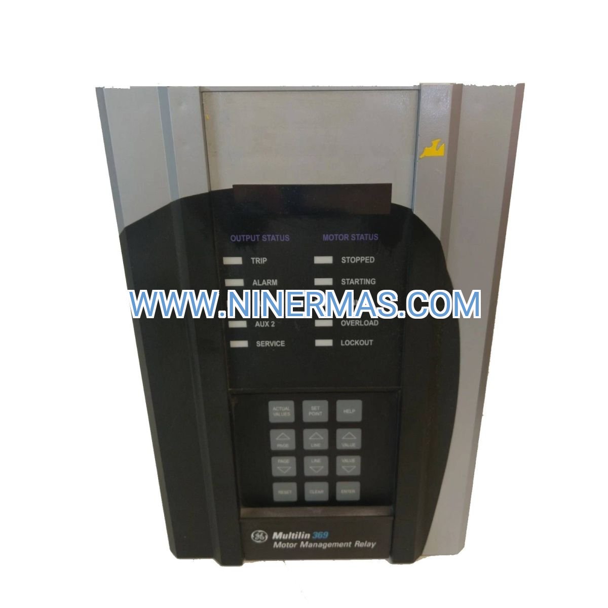
GE 369-HI-R-0-0-E-0-E Digital Motor Protection Relay (Industrial-Grade Motor Safeguarding)
The GE 369-HI-R-0-0-E-0-E represents a proven solution in digital motor protection technology, engineered to defend AC motors against thermal damage, electrical faults, and mechanical failures across industrial environments. Built on GE Multilin's 369 platform, this relay integrates adaptive thermal modeling with real-time fault detection to extend motor lifespan and reduce unplanned downtime.
Designed for facilities managing critical rotating equipment, this protection relay addresses the operational challenges of motor overheating, phase imbalance, ground faults, and locked rotor conditions. Whether you operate pumping stations, conveyor systems, or process machinery, the 369-HI-R-0-0-E-0-E delivers the precision monitoring required to prevent catastrophic motor failures.
With Modbus RTU connectivity and a comprehensive protection suite, this relay serves as the cornerstone of intelligent motor management systems. From fractional horsepower applications to multi-thousand HP installations, the 369 series provides scalable protection that adapts to your operational requirements while maintaining compliance with UL, CSA, and CE safety standards.
Core Features & Technical Advantages
→ Adaptive Thermal Overload Modeling
Utilizes RTD-based algorithms that mirror actual motor heating curves, preventing nuisance trips while ensuring protection against sustained overload conditions. This intelligent thermal management extends motor service life by 15-25% compared to conventional bimetallic overload devices.
→ Multi-Function Fault Detection
Simultaneously monitors ground fault currents, phase loss events, current imbalance, undercurrent conditions, and locked rotor scenarios. Each protection element operates independently with adjustable trip thresholds and time delays, providing customized safeguarding for specific motor applications.
→ Modbus RTU Integration
RS-485 serial communication enables seamless data exchange with SCADA systems, PLCs, and HMI platforms. Access real-time current readings, thermal capacity utilization, fault logs, and operational statistics remotely without interrupting motor operation.
✓ Wide Voltage & Current Compatibility
Accepts 90-600V AC voltage inputs and 0.2-5A CT secondary currents, accommodating motors from 1HP to 5000HP+ when paired with appropriately rated current transformers. This flexibility eliminates the need for multiple relay models across diverse motor inventories.
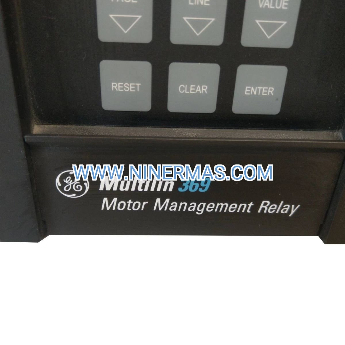
✓ 40-Character LCD Interface
Front-panel display provides instant access to motor status, protection settings, and diagnostic data. Navigate configuration menus and review fault history without external programming tools, reducing commissioning time by 30-40%.
✓ Harsh Environment Durability
Operates reliably across -40°C to +70°C temperature ranges with 90-250V AC/DC universal power supply. Panel-mount design fits standard DIN cutouts for straightforward retrofit installations in existing motor control centers.
Industrial Application Scenarios
Water & Wastewater Treatment
Protects submersible pump motors, aerator drives, and clarifier mechanisms where continuous operation is essential. The relay's ground fault sensitivity detects insulation degradation before catastrophic failure occurs, preventing environmental contamination and costly emergency repairs in municipal treatment facilities.
Manufacturing & Process Industries
Safeguards conveyor motors, mixer drives, and material handling equipment in food processing, pharmaceutical production, and chemical manufacturing. Real-time thermal monitoring prevents production stoppages by identifying abnormal loading patterns that indicate mechanical binding or product buildup.
HVAC & Building Systems
Monitors chiller compressors, cooling tower fans, and air handling unit motors in commercial buildings and data centers. Phase imbalance detection prevents single-phasing damage during utility power quality events, maintaining climate control reliability for temperature-sensitive operations.
Mining & Heavy Industry
Defends crusher motors, mill drives, and ventilation fans against the extreme loading conditions common in extraction and processing operations. Locked rotor protection responds within milliseconds to mechanical jamming events, preventing motor burnout and reducing maintenance costs by 20-35%.
Oil & Gas Facilities
Provides comprehensive protection for pipeline pump motors, compressor drives, and separator equipment in upstream and midstream operations. The relay's wide operating temperature range ensures reliable performance in both arctic and desert environments where conventional protection devices fail.
Technical Parameters & Selection Guide
| Specification | Value | Application Notes |
|---|---|---|
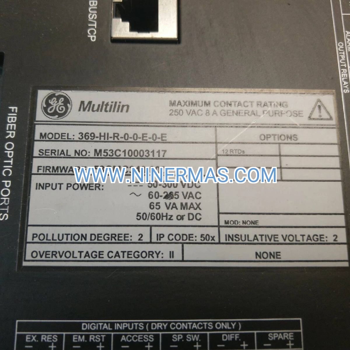
| Model Designation | 369-HI-R-0-0-E-0-E | Specific I/O and communication configuration |
| Protection Class | Digital Motor Management | Multilin 369 series platform |
| Current Input | 0.2-5A CT Secondary | Requires external CTs; select ratio based on motor FLA |
| Voltage Monitoring | 90-600V AC | Direct connection for motors ≤600V; use PTs for higher voltages |
| Communication | Modbus RTU (RS-485) | Supports up to 32 devices per network segment |
| Display | 40-Character Backlit LCD | Visible in low-light industrial environments |
| Operating Range | -40°C to +70°C | Suitable for outdoor enclosures and harsh environments |
| Control Power | 90-250V AC/DC Universal | Eliminates need for separate power supplies |
| Protection Functions | Thermal, Ground Fault, Phase Loss, Undercurrent, Locked Rotor | All elements independently adjustable |
| Mounting | Panel Mount (DIN Standard) | Fits existing motor control center cutouts |
| Certifications | UL Listed, CSA Certified, CE Marked | Meets North American and European safety standards |
Selection Criteria: Choose current transformer ratios that position motor full-load current between 50-80% of CT secondary rating. For motors with high starting currents (>6x FLA), verify locked rotor time delay settings accommodate starting duration. When integrating with SCADA systems, confirm Modbus register mapping compatibility with your supervisory platform.
Extended Capabilities
Event Recording & Diagnostics
The relay maintains a comprehensive fault log capturing the last 40 trip events with time stamps, current magnitudes, and thermal capacity at fault occurrence. This historical data enables root cause analysis of recurring motor problems and supports predictive maintenance strategies.
Programmable Output Contacts
Configurable relay outputs can trigger alarms, initiate backup equipment, or signal building management systems when protection thresholds are approached. This early warning capability allows operators to address developing problems before motor shutdown becomes necessary.
Custom Protection Curves
Adjust thermal time constants, pickup levels, and trip delays to match specific motor characteristics and application requirements. This customization ensures optimal protection without sacrificing operational flexibility for motors with unusual duty cycles or loading patterns.
Delivery Timeline & Service Commitment
Standard Delivery: In-stock units ship within 1-2 business days via express courier with tracking. Typical transit time to major industrial centers ranges from 3-7 days depending on destination.
Custom Configuration: Factory-programmed relays with customer-specific settings available with 7-10 business day lead time. Submit motor nameplate data and protection requirements for pre-commissioning configuration service.
Warranty Coverage: 12-month manufacturer warranty covers defects in materials and workmanship. Extended warranty options available for critical applications requiring enhanced support.
Technical Support: Our application engineering team provides configuration assistance, Modbus integration guidance, and troubleshooting support throughout the product lifecycle. Access to GE Multilin technical documentation, wiring diagrams, and software tools included with purchase.
Documentation Package: Each relay ships with installation manual, quick start guide, Modbus register map, and configuration worksheet. Digital resources include CAD drawings, protection coordination curves, and sample SCADA integration code.
Frequently Asked Questions
What motor horsepower range does the GE 369-HI-R-0-0-E-0-E protect?
This relay protects motors from fractional HP to over 5000HP when paired with correctly sized current transformers. The 0.2-5A CT secondary input accommodates a wide range of motor sizes—select CT primary ratings that result in 2.5-4A secondary current at motor full load for optimal accuracy.
How does Modbus RTU communication integrate with existing control systems?
The RS-485 Modbus interface connects directly to PLC communication modules, SCADA RTUs, or industrial Ethernet gateways. The relay supports standard Modbus function codes (03, 04, 06, 16) and provides read access to real-time measurements, protection status, and fault logs. Configuration requires setting a unique Modbus address (1-247) and matching baud rate (9600-19200 typical).
Can this relay replace thermal overload relays in existing motor starters?
Yes, the 369-HI-R-0-0-E-0-E provides superior protection compared to conventional thermal overload relays. Installation requires adding current transformers in the motor circuit and connecting the relay's trip output to the starter control circuit. The digital thermal model offers more accurate protection and eliminates the drift and calibration issues common with bimetallic overload devices.
What's the difference between this model and other 369 series variants?
The model suffix (HI-R-0-0-E-0-E) specifies the relay's I/O configuration, communication options, and display type. The "HI" indicates high-range current inputs, "R" denotes specific relay output configuration, and the "E" positions specify communication and power supply options. Consult the GE Multilin 369 selection guide to match exact requirements.
Does the relay require external current transformers?
Yes, external CTs with 5A or 1A secondary output are required for current measurement. The relay does not include internal current sensors. Select CT accuracy class 0.5 or better for protection applications, and ensure CT burden ratings accommodate the relay's input impedance plus lead wire resistance.
How do I configure thermal overload protection settings?
Thermal protection setup requires entering motor nameplate data via the front panel: full load amps (FLA), service factor, and thermal time constant (typically 5-20 minutes for NEMA motors). The relay calculates thermal capacity in real-time based on current flow and ambient temperature compensation. Advanced users can access custom thermal curve programming through the configuration menu.
Ready to Protect Your Critical Motors?
Secure your industrial motor assets with proven GE Multilin protection technology. Contact our technical sales team for application-specific configuration guidance, volume pricing, or integration support for multi-motor installations.
Request a quote today or speak with our motor protection specialists to ensure optimal relay selection for your specific application requirements.
© 2026 NINERMAS COMPANY LIMITED. All rights reserved.
Original Source: https://ninermas.com
Contact: sale@ninermas.com | +0086 187 5021 5667


Contact Info
-
Address:22 / F, South Wo Hang building, 148 Wing Lok Street, Sheung Wan, Western District, Hong Kong
-
Phone:+8618750215667
-
Email: