Description
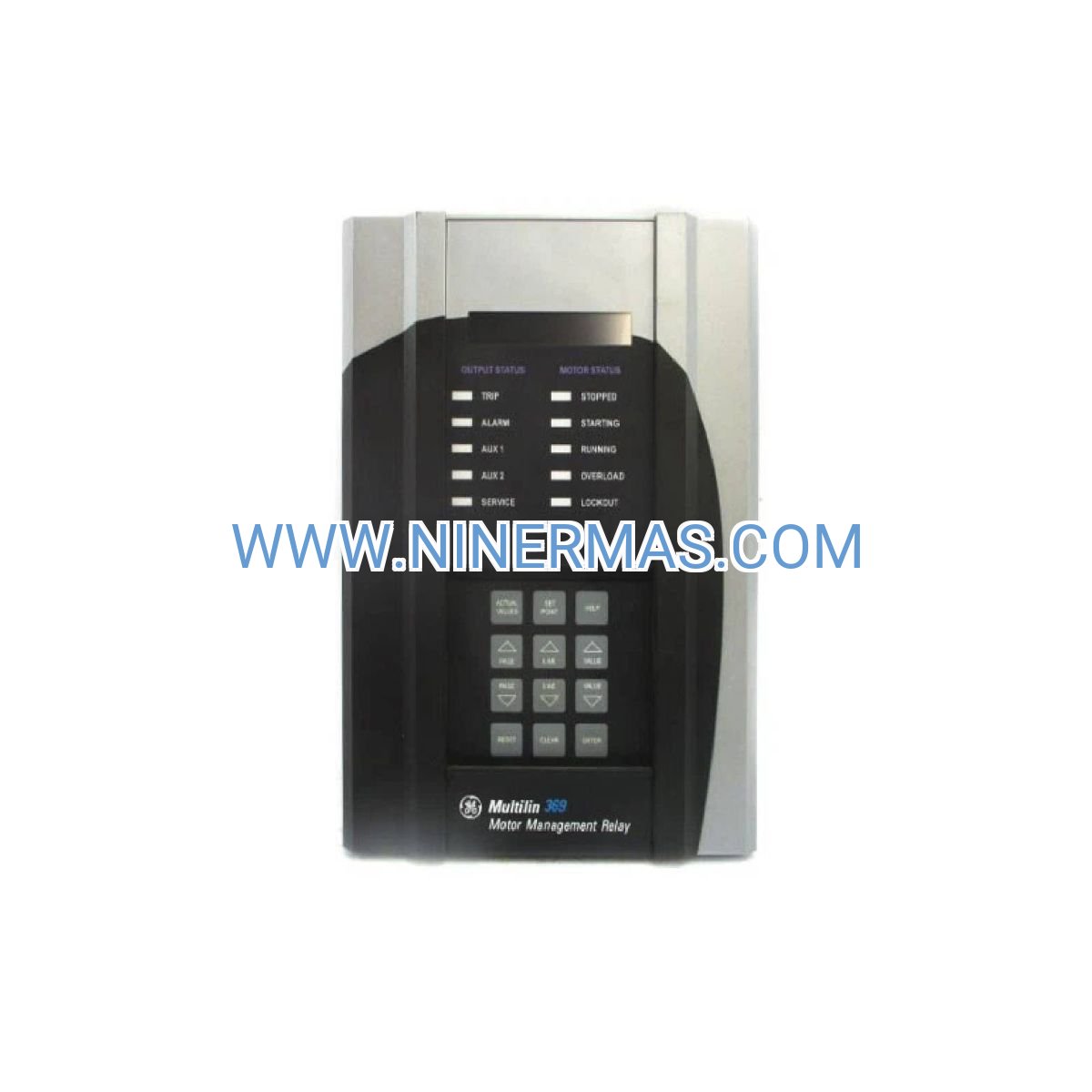
GE 369-HI-0-B-F-0 Digital Motor Protection Relay (Industrial-Grade Monitoring System)
The GE 369-HI-0-B-F-0 is a sophisticated digital motor protection relay engineered to safeguard AC motors in demanding industrial environments. This Multilin series device combines precision monitoring, intelligent fault detection, and predictive maintenance capabilities into a single compact unit. Designed for facilities where motor downtime translates to significant operational losses, this relay delivers comprehensive protection while maximizing equipment utilization and extending motor service life.
Industrial operators across manufacturing, energy, and process industries rely on the 369-HI-0-B-F-0 to prevent catastrophic motor failures, reduce maintenance costs, and ensure continuous production. The relay's adaptive thermal modeling algorithm accurately tracks motor temperature in real-time, preventing thermal damage while allowing motors to operate at optimal capacity. With integrated communication capabilities and extensive metering functions, this device serves as both a protective guardian and an intelligent data source for modern industrial control systems.
Whether you're protecting high-value motors driving critical pumps, compressors, or conveyors, the GE 369-HI-0-B-F-0 provides the reliability and intelligence your operations demand. Its proven track record in harsh industrial environments, combined with comprehensive diagnostic features, makes it an essential component of any motor management strategy.
Technical Specifications & Selection Guide
| Parameter | Specification |
|---|---|
| Catalog Number | 369-HI-0-B-F-0 |
| Product Series | GE Multilin 369 Motor Management |
| Control Power Supply | 90-300V AC/DC (Universal Input) |
| Current Measurement Range | 0.2A to 13,000A (via external CTs) |
| Operating Frequency | 45-65 Hz (Configurable) |
| Display Interface | 40-Character Backlit LCD with Navigation Keys |
| Communication Protocol | RS485 Modbus RTU |
| Environmental Rating | -40°C to +70°C Operating Range |
| Protection Functions | Thermal Overload, Locked Rotor, Phase Imbalance, Ground Fault, Under/Overvoltage, Jam Detection |
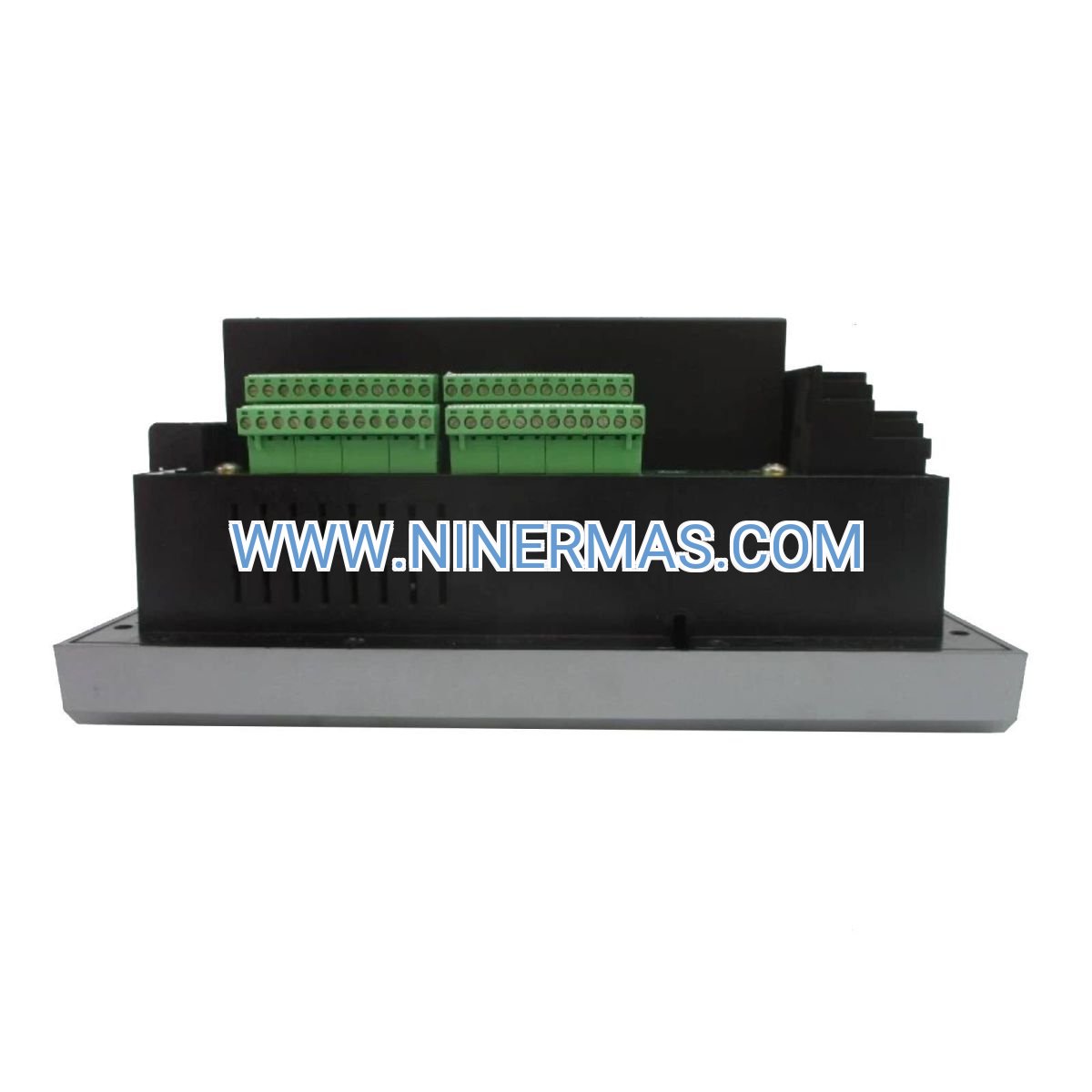
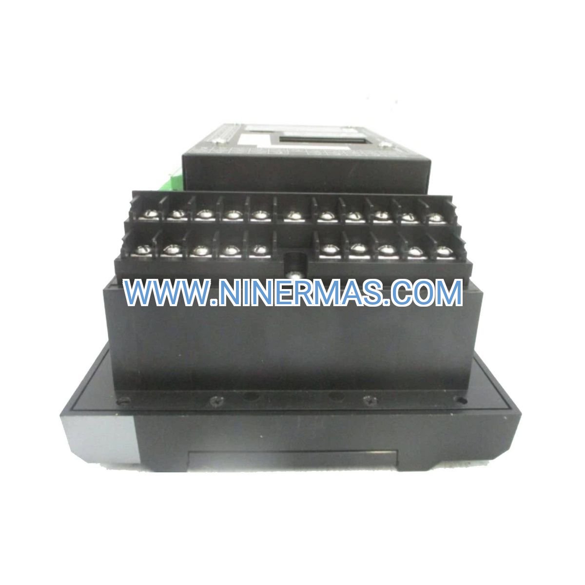
| Mounting Configuration | Panel Mount (Standard DIN Cutout) |
| Compliance Certifications | UL Listed, CSA Certified, CE Marked |
Selection Criteria: Choose the 369-HI-0-B-F-0 for applications requiring high-range current inputs (HI designation), basic I/O configuration (0-B), and Modbus communication (F-0 suffix). For applications requiring RTD temperature inputs, consider alternative model configurations within the 369 series. Verify current transformer ratios match your motor nameplate ratings for accurate protection coordination.
Core Protection Features & Business Value
→ Adaptive Thermal Modeling Technology – Continuously calculates motor thermal capacity using sophisticated algorithms that account for load history, ambient conditions, and cooling effectiveness. This prevents nuisance trips while ensuring motors never exceed safe thermal limits, reducing downtime by up to 40% compared to conventional thermal overload devices.
→ Multi-Function Fault Detection System – Monitors phase current imbalance, ground fault conditions, locked rotor scenarios, and jam situations simultaneously. Early fault detection prevents catastrophic failures, with studies showing protected motors lasting 25-35% longer than unprotected equivalents.
→ Integrated Metering & Diagnostics – Provides real-time visibility into motor current, voltage, power factor, energy consumption, and operating hours. This data enables predictive maintenance scheduling, reducing emergency repair costs by 50-60% and improving maintenance planning efficiency.
→ Industrial Communication Integration – RS485 Modbus RTU connectivity allows seamless integration with SCADA systems, PLCs, and building management platforms. Remote monitoring capabilities reduce site visits by 70% and enable centralized fleet management across multiple facilities.
✓ User-Configurable Protection Settings – Programmable trip curves, pickup values, and time delays ensure protection coordination with upstream devices. Flexible configuration reduces commissioning time by 30-40% compared to fixed-setting relays.
✓ Event Recording & Waveform Capture – Stores fault events with time-stamped data and waveform snapshots for post-incident analysis. This forensic capability accelerates troubleshooting, reducing mean time to repair (MTTR) by 45-55%.
Industrial Application Scenarios
Manufacturing & Production Facilities
Critical conveyor systems, material handling equipment, and process machinery require uninterrupted operation. The 369-HI-0-B-F-0 protects motors driving these systems while providing operational data for production optimization. In automotive manufacturing plants, these relays have reduced motor-related production stoppages by 65%, translating to millions in avoided downtime costs annually.
Oil, Gas & Petrochemical Operations
Harsh environments with extreme temperatures, vibration, and electrical noise demand robust protection solutions. Pump motors, compressor drives, and fan systems in refineries and processing plants benefit from the relay's wide operating temperature range and noise-immune design. Operators report 80% reduction in motor failures in corrosive atmospheres when properly protected.
Water & Wastewater Treatment Plants
Municipal water systems depend on reliable pump operation for public health and safety. The 369-HI-0-B-F-0's ground fault protection and phase loss detection prevent pump damage from electrical anomalies common in wet environments. Treatment facilities using these relays achieve 99.7% pump availability rates, exceeding regulatory requirements.
Power Generation & Distribution
Auxiliary motors in power plants—cooling water pumps, fuel handling systems, and ventilation fans—require protection that won't compromise plant availability. The relay's selective coordination capabilities ensure only faulted equipment is isolated, maintaining grid stability. Power plants report 40% fewer forced outages related to auxiliary motor failures.
Mining & Material Processing
Crusher drives, mill motors, and conveyor systems in mining operations face severe mechanical stress and electrical transients. The 369-HI-0-B-F-0's locked rotor and jam protection detect mechanical binding before catastrophic damage occurs, reducing equipment replacement costs by 50-70% in heavy-duty applications.
Extended Capabilities & System Integration
SCADA & IoT Connectivity: Modbus RTU protocol enables integration with modern industrial IoT platforms, allowing cloud-based analytics, mobile monitoring, and AI-driven predictive maintenance. Connect to enterprise asset management systems for automated work order generation based on motor operating conditions.
Multi-Motor Coordination: Deploy multiple 369-HI-0-B-F-0 relays across motor control centers with centralized monitoring. Network up to 247 devices on a single Modbus segment for facility-wide motor fleet management. Standardizing on a single relay platform reduces spare parts inventory by 60% and simplifies technician training.
Custom Protection Schemes: Advanced users can configure custom logic using the relay's programmable outputs and inputs. Implement motor sequencing, load shedding, or automatic restart schemes tailored to specific process requirements. Engineering services available for complex application programming.
Delivery Timeline & Service Commitment
Standard Delivery: In-stock units ship within 1-2 business days via express courier. Typical delivery to major industrial centers: 3-5 business days domestic, 7-10 business days international. Expedited same-day shipping available for critical outages (additional fees apply).
Custom Configuration: Factory-configured units with customer-specific settings available with 10-15 business day lead time. Pre-commissioning services include protection study review, settings calculation, and configuration file documentation.
Warranty Coverage: Comprehensive 12-month manufacturer warranty covers defects in materials and workmanship. Extended warranty programs available for up to 5 years, including advance replacement and priority technical support.
Technical Support: Lifetime application engineering support included with purchase. Access to protection coordination studies, settings recommendations, and troubleshooting assistance. On-site commissioning support available in select regions (quoted separately).
Documentation Package: Each relay ships with installation manual, quick start guide, Modbus register map, and settings worksheet templates. CAD drawings, protection curves, and sample ladder logic available for download.
Frequently Asked Questions
How does the 369-HI-0-B-F-0 compare to traditional thermal overload relays for motor protection applications?
Digital motor protection relays like the 369-HI-0-B-F-0 offer significant advantages over electromechanical thermal overloads. While traditional devices use bimetallic strips that respond only to current magnitude, the 369 employs sophisticated thermal modeling that accounts for motor load history, service factor, and ambient temperature. This results in 40-50% fewer nuisance trips while providing superior protection against thermal damage. Additionally, the 369 includes ground fault protection, phase imbalance detection, and diagnostic capabilities impossible with conventional overloads.
What current transformer ratios are compatible with this relay model for accurate motor monitoring?
The 369-HI-0-B-F-0 accepts CT secondary currents of 5A or 1A (field-selectable) with primary ratios from 50:5 to 13,000:5. For optimal accuracy, select CT ratios where normal motor full-load current falls between 50-100% of the CT secondary rating. For example, a 100HP motor with 124A FLA would use a 150:5 CT ratio. Oversized CTs (where motor current is <20% of CT rating) can cause measurement errors and should be avoided. Consult the relay manual's CT selection guide or contact technical support for specific application assistance.
Can this motor protection relay integrate with variable frequency drive systems for comprehensive protection?
Yes, the 369-HI-0-B-F-0 includes VFD-compatible protection algorithms that account for the unique characteristics of inverter-fed motors. When protecting VFD-driven motors, configure the relay for "VFD mode" to disable voltage-based protections (which are handled by the drive) while maintaining critical thermal and current-based protections. The relay's Modbus communication can interface with VFD control networks for coordinated motor management. For applications with regenerative drives or multi-motor drives, consult application engineering for proper protection coordination.
What are the power consumption requirements and backup power considerations for continuous motor monitoring?
The relay draws approximately 15W from the control power supply under normal operation. The universal 90-300V AC/DC input accepts standard control voltages without external transformers. For critical applications requiring protection during power disturbances, the relay maintains full functionality with control power as low as 80V AC/DC. Many users install UPS systems on motor control center control power buses to ensure protection remains active during brief power interruptions. The relay's low power consumption allows dozens of units to operate from a single 500VA UPS.
How do I configure remote monitoring and integrate this relay with existing SCADA infrastructure?
The 369-HI-0-B-F-0's RS485 Modbus RTU port supports baud rates from 9600 to 115200 bps with configurable device addresses (1-247). Connect the relay to your SCADA system's Modbus master using standard twisted-pair cable (Belden 9841 or equivalent). The relay exposes over 200 Modbus registers containing real-time measurements, protection status, and alarm conditions. Most SCADA platforms (Wonderware, Ignition, FactoryTalk) include pre-built Modbus drivers. For Ethernet connectivity, add a Modbus RTU-to-TCP gateway. Complete Modbus register maps and sample SCADA tag databases are available in the technical documentation section.
What installation clearances and environmental conditions must be maintained for reliable long-term operation?
Maintain minimum 50mm (2") clearance on all sides for adequate ventilation and heat dissipation. The relay operates reliably in ambient temperatures from -40°C to +70°C, but for maximum component life, limit sustained operation above 60°C. In high-vibration environments (>2g), use vibration-dampening panel mounts. The relay meets IP20 front panel rating when properly installed; for IP54 protection, use optional gasket kits. Avoid installation near high-frequency VFDs or welding equipment without proper EMI filtering. In corrosive atmospheres, apply conformal coating to circuit boards (factory service available).
Secure Your Motor Assets Today
Don't wait for costly motor failures to impact your operations. The GE 369-HI-0-B-F-0 Digital Motor Protection Relay delivers proven protection technology trusted by thousands of industrial facilities worldwide. Our technical team is ready to assist with application selection, protection coordination studies, and implementation support.
Ready to protect your critical motors? Contact our motor protection specialists for personalized recommendations, quantity pricing, or technical consultation. Same-day quotes available for urgent projects.
© 2026 NINERMAS COMPANY LIMITED. All rights reserved.
Original Source: https://ninermas.com
Contact: sale@ninermas.com | +0086 187 5021 5667


Contact Info
-
Address:22 / F, South Wo Hang building, 148 Wing Lok Street, Sheung Wan, Western District, Hong Kong
-
Phone:+8618750215667
-
Email: