Description
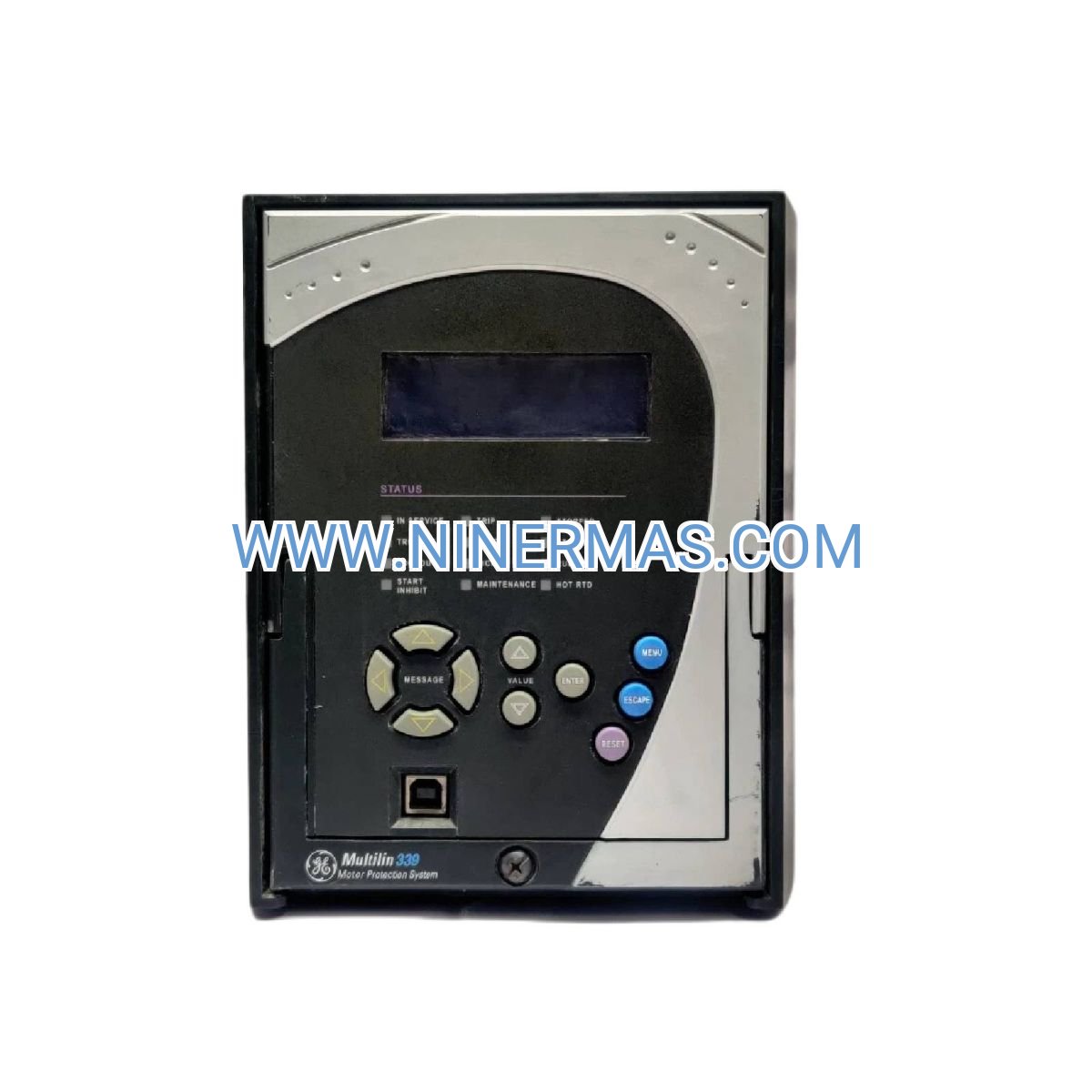
GE 339-E Motor Protection Relay (Industrial-Grade Motor Control System)
The GE 339-E Motor Protection Relay is an industrial control device designed for comprehensive AC motor protection and performance monitoring. Through advanced microprocessor-based control, PLC-compatible communication protocols, and adaptive thermal modeling algorithms, this relay delivers real-time fault detection, predictive diagnostics, and automated protective shutdown capabilities for critical motor-driven equipment.
Suitable for manufacturing plants, municipal water treatment facilities, HVAC systems, material handling operations, and process automation environments, the relay addresses common challenges including thermal overload damage, phase imbalance failures, ground fault hazards, locked rotor conditions, and unplanned downtime caused by inadequate motor monitoring. It provides early warning indicators and configurable alarm thresholds to prevent catastrophic motor failures.
Leveraging standardized design with field-customizable parameter sets, this protection relay offers rapid commissioning, multi-protocol communication (Modbus RTU, Ethernet/IP), intuitive LCD interface, comprehensive event logging, and compatibility with existing motor control centers. Ideal for consulting engineers, system integrators, OEM equipment manufacturers, and facility maintenance teams requiring reliable motor asset protection. Contact our application engineers for load-specific configuration recommendations and technical specifications.
Core Functions & Advantages
Adaptive Thermal Overload Protection
Utilizes real-time thermal capacity algorithms that continuously calculate motor winding temperature based on load current, ambient conditions, and thermal time constants. This intelligent modeling prevents thermal stress accumulation while eliminating nuisance trips common with conventional bimetallic overload devices, extending motor service life by 20-35%.
Multi-Function Fault Detection
Integrated protection suite monitors phase loss, voltage imbalance, undervoltage/overvoltage conditions, ground fault currents, locked rotor scenarios, and phase reversal. Each protection function features independently adjustable trip thresholds and time delays, allowing precise coordination with upstream protective devices and downstream equipment characteristics.
Industrial Communication Protocols
Native support for Modbus RTU (RS-485) and Ethernet/IP enables seamless integration with SCADA systems, distributed control systems (DCS), programmable logic controllers (PLCs), and building management systems (BMS). Real-time data transmission includes motor current, voltage, power factor, operating hours, trip history, and thermal capacity status for predictive maintenance programs.
Comprehensive Event & Alarm Management
Non-volatile memory stores up to 512 time-stamped events including fault conditions, parameter changes, and operational anomalies. Configurable alarm outputs (relay contacts, digital signals) provide local and remote notification of pre-alarm conditions, allowing operators to take corrective action before protective shutdown occurs.
User-Friendly Configuration Interface
Backlit LCD display with multi-language support (English, Spanish, French, German, Chinese) presents real-time operating parameters, fault diagnostics, and setup menus. Front-panel keypad navigation eliminates the need for external programming devices during commissioning and troubleshooting, reducing installation time by approximately 40%.
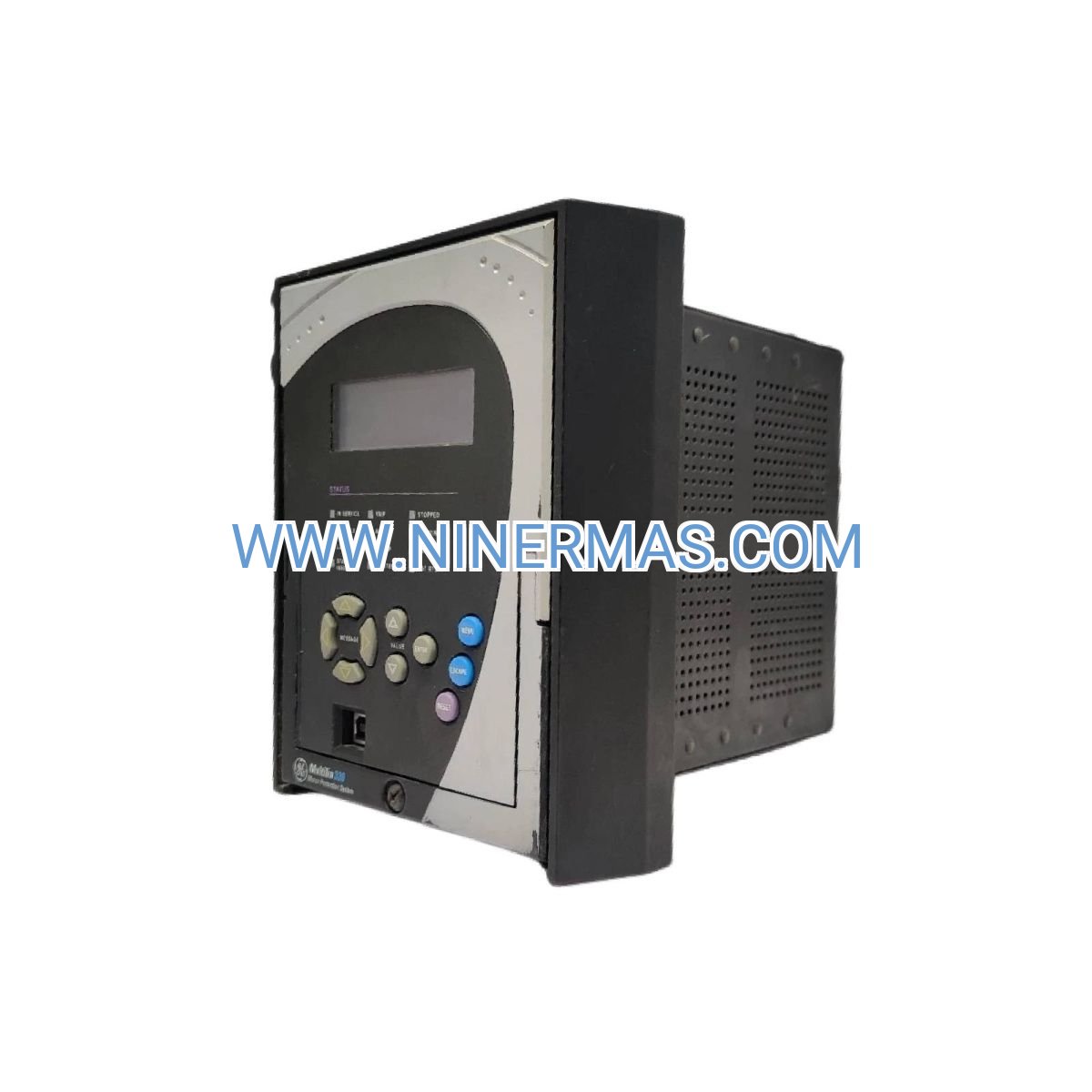
Robust Environmental Design
Engineered for harsh industrial environments with operating temperature range of -40°C to +70°C, conformal-coated circuit boards for moisture and contaminant resistance, and EMC compliance to IEC 61000-4 standards. Panel-mount design with IP20 front protection (IP54 available with optional gasket kit) suits both control room and field-mounted applications.
Typical Application Scenarios
This motor protection relay is engineered for applications demanding high reliability, continuous operation, and advanced diagnostic capabilities, particularly in:
Water & Wastewater Treatment Systems
Protects centrifugal pumps, submersible pumps, and blower motors in municipal water supply, sewage lift stations, and industrial wastewater treatment plants. Prevents dry-run damage through low-current detection and provides remote monitoring integration with SCADA systems for unmanned pump stations.
HVAC & Building Automation
Safeguards chiller compressors, cooling tower fans, air handling unit motors, and boiler circulation pumps in commercial buildings, hospitals, data centers, and institutional facilities. Thermal modeling accounts for variable load profiles and frequent start-stop cycles typical in HVAC applications, reducing false trips by 60% compared to fixed-curve overload relays.
Manufacturing & Process Industries
Ensures continuous operation of conveyor drives, mixer motors, extruder drives, and material handling equipment in food processing, chemical manufacturing, automotive assembly, and packaging operations. Event logging and predictive maintenance alerts minimize unscheduled downtime and support lean manufacturing initiatives.
Oil & Gas Production Facilities
Monitors compressor motors, pipeline pumps, and drilling equipment in upstream production, midstream transportation, and downstream refining operations. Hazardous location compatibility (when installed in appropriate enclosures) and extended temperature ratings suit offshore platforms and remote wellhead installations.
Mining & Material Processing
Provides rugged protection for crusher motors, conveyor systems, grinding mills, and ventilation fans in underground mines, surface operations, and mineral processing plants. Vibration-resistant construction and high-noise immunity ensure reliable operation in electrically harsh environments with frequent VFD switching and large inductive loads.
Technical Parameters & Selection Guide
To facilitate engineering design and equipment specification, we provide standardized configuration options with field-customizable parameters. The relay accommodates diverse motor ratings and application requirements through flexible current transformer (CT) ratios and programmable protection settings.
| Parameter | Specification Range |
|---|---|
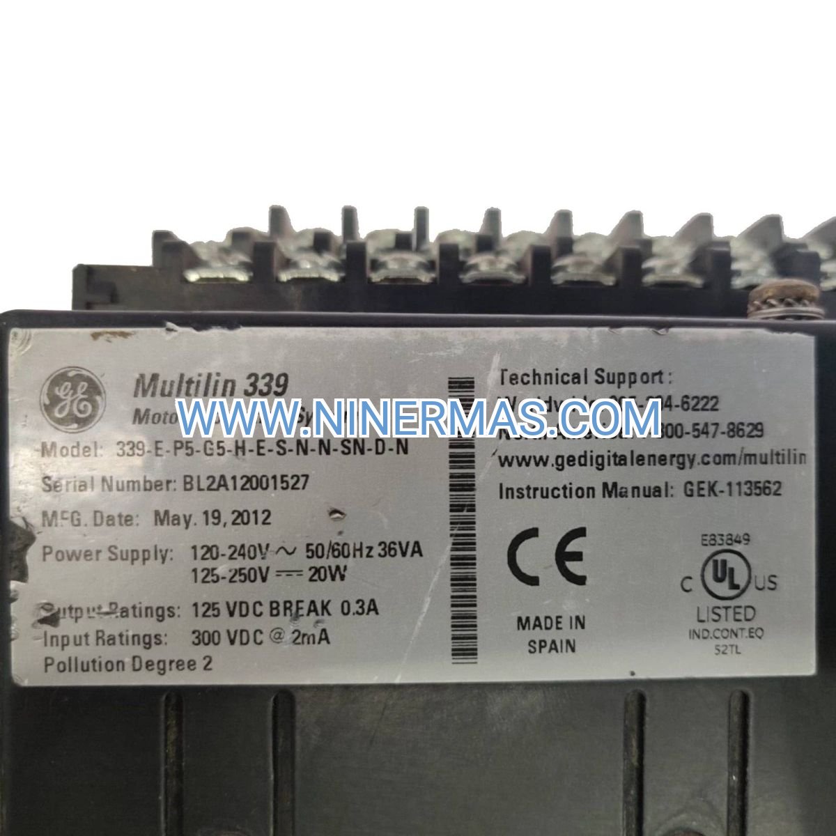
| Model Designation | 339-E-P5-G5-H-E-S-N-N-SN-D-N |
| Control Power Supply | 100-240V AC/DC (±15%), 50/60 Hz, 15W max |
| Motor Current Range | 0.4A to 820A (via external CT, ratios 5A or 1A secondary) |
| Voltage Monitoring | Phase-to-phase: 100-690V AC (direct or via PT) |
| Protection Functions | Thermal overload (Class 10/20/30), phase loss, voltage imbalance, under/overvoltage, ground fault (5-100% FLA), locked rotor, phase reversal, undercurrent |
| Communication Interfaces | Modbus RTU (RS-485, up to 115.2 kbps), Ethernet/IP (10/100 Mbps) |
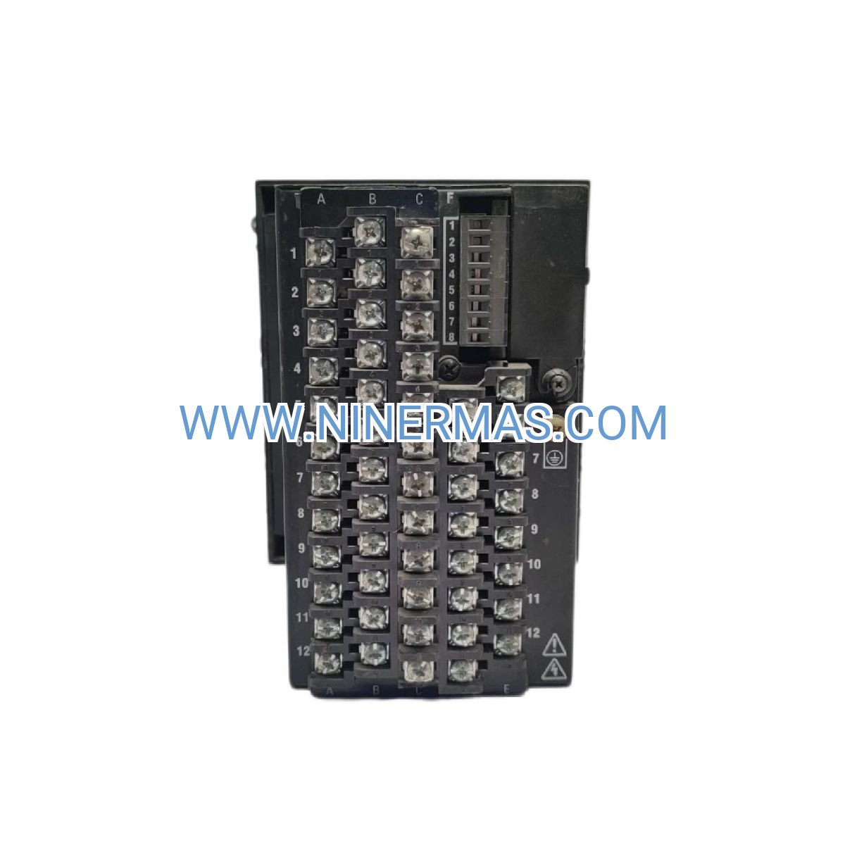
| Relay Output Contacts | 4x Form C (SPDT), 5A @ 250V AC resistive, 100,000 operations |
| Digital Inputs | 4x programmable (reset, enable, external trip, etc.) |
| Display Type | 128x64 pixel LCD with LED backlight, multi-language support |
| Operating Temperature | -40°C to +70°C (-40°F to +158°F) |
| Storage Temperature | -50°C to +85°C |
| Humidity Range | 5% to 95% RH, non-condensing |
| Mounting Configuration | Panel cutout 92mm x 92mm, depth 165mm, DIN rail adapter optional |
| Enclosure Rating | Front: IP20 (NEMA 1), Rear terminals: IP00 |
| Compliance Certifications | UL 508, CE (LVD, EMC), CSA C22.2, IEC 61010-1, IEC 60255 |
| MTBF (Mean Time Between Failures) | >150,000 hours @ 40°C ambient |
Selection Considerations
When specifying this motor protection relay, engineers should evaluate: motor full-load current (FLA) and service factor, available control power voltage, required communication protocol compatibility with existing automation infrastructure, ambient temperature at installation location, desired protection class (thermal curve), ground fault sensitivity requirements, and number of auxiliary contacts needed for alarm/status indication. For motors above 500 HP or applications with complex starting sequences (soft-start, autotransformer, wye-delta), consult factory application engineers for advanced configuration guidance including custom thermal models and coordination studies.
Current Transformer (CT) Sizing
Proper CT selection is critical for accurate protection. Recommended CT ratios should provide secondary current between 0.5A and 5A at motor full-load conditions. For example, a 100 HP motor (approximately 125A FLA @ 480V) would typically use 150:5 or 200:5 CT ratio. Ground fault detection requires separate zero-sequence CT or residual connection of phase CTs depending on system grounding configuration.
Extended Capabilities & Integration Options
Predictive Maintenance Analytics
Continuous monitoring of motor operating parameters enables condition-based maintenance strategies. The relay tracks cumulative thermal stress (thermal capacity used), number of starts per hour, running hours, and trip frequency. When integrated with plant asset management systems via Modbus or Ethernet, this data supports predictive algorithms that forecast bearing failures, insulation degradation, and optimal maintenance intervals—reducing maintenance costs by 25-40% compared to time-based schedules.
Load Profiling & Energy Management
Built-in power metering functions measure active power (kW), reactive power (kVAR), power factor, and energy consumption (kWh). This data integrates with energy management systems to identify inefficient motors, optimize load distribution, and support ISO 50001 energy management certification requirements. Demand response programs benefit from relay-provided load shedding signals during peak pricing periods.
Multi-Motor Coordination
For applications with multiple motors in sequential or parallel operation (pump stations, compressor arrays, conveyor systems), the relay's programmable logic and communication capabilities enable coordinated control schemes. Lead-lag rotation, duty-standby switching, and cascade starting sequences can be implemented through networked relay configurations, eliminating the need for separate sequencing controllers.
Cybersecurity Features
Password-protected configuration menus prevent unauthorized parameter changes. Ethernet communication supports VLAN segmentation and MAC address filtering for industrial network security. Audit trail logging records all configuration changes with user identification and timestamps, supporting compliance with IEC 62443 industrial cybersecurity standards.
Delivery, Service & Quality Assurance
Lead Times & Availability
Standard catalog configurations (model 339-E-P5-G5-H-E-S-N-N-SN-D-N) typically ship within 3-5 business days from regional distribution centers. Custom-configured units with specific firmware versions, communication protocols, or factory-programmed settings require 10-15 business days. Expedited processing available for critical outage situations with 24-48 hour emergency shipment options (subject to stock availability and destination).
Warranty Coverage
All GE Multilin motor protection relays include a comprehensive 24-month manufacturer warranty from date of shipment, covering defects in materials, workmanship, and component failures under normal operating conditions. Warranty service includes no-cost repair or replacement, return shipping, and technical support for troubleshooting. Extended warranty programs (up to 5 years) available for mission-critical applications with annual preventive maintenance contracts.
Technical Support & Commissioning Assistance
Factory-trained application engineers provide pre-sale consultation for protection coordination studies, CT sizing calculations, and communication network design. Post-sale support includes remote configuration assistance, firmware updates, and troubleshooting guidance via phone, email, or web portal. On-site commissioning services available for complex installations, multi-relay systems, or facilities requiring witnessed acceptance testing (FAT/SAT protocols).
Documentation Package
Each relay ships with complete technical documentation including: installation manual with dimensional drawings and panel cutout templates, wiring diagrams for typical applications (DOL, star-delta, soft-start), quick-start programming guide, Modbus register map and communication protocol specifications, and calibration certificate with test data. Digital documentation library accessible via manufacturer support portal includes application notes, firmware release notes, and CAD files (DWG, DXF formats).
Compliance & Testing
Manufactured in ISO 9001:2015 certified facilities with 100% functional testing prior to shipment. Each unit undergoes automated test sequences verifying protection accuracy, communication functionality, relay contact operation, and environmental stress screening. Type-tested to IEC 60255 standards for vibration, shock, temperature cycling, and electromagnetic compatibility. Third-party certifications (UL, CSA, CE) maintained through ongoing compliance audits and design control processes.
Frequently Asked Questions (FAQ)
Q: How does the GE 339-E motor protection relay determine optimal thermal trip settings?
A: The relay employs adaptive thermal modeling based on motor nameplate data (FLA, service factor, thermal time constant) entered during commissioning. The algorithm continuously calculates rotor and stator thermal capacity using I²t integration, accounting for ambient temperature compensation and cooling time constants. Unlike fixed thermal curves, this approach adapts to actual operating conditions—preventing nuisance trips during legitimate overload events (such as high-inertia starting) while providing faster protection during stalled rotor or locked conditions. Engineers can select from Class 10, 20, or 30 thermal curves to match motor thermal withstand characteristics.
Q: Can this relay be retrofitted into existing motor control centers without extensive rewiring?
A: Yes, the 339-E relay is designed for retrofit compatibility with standard 92mm x 92mm panel cutouts (common in motor control centers worldwide). Existing overload relay wiring can often be reused—the relay accepts standard 5A or 1A secondary CT inputs and provides Form C relay contacts compatible with most control circuits. The universal control power input (100-240V AC/DC) eliminates the need for separate power supplies in mixed-voltage panels. For communication integration, the relay's Modbus RTU interface uses simple two-wire RS-485 connections that can be daisy-chained across multiple devices without dedicated network infrastructure.
Q: What is the typical energy savings achieved by implementing advanced motor protection relays?
A: While the relay itself is a protective device rather than an energy-saving device, the comprehensive monitoring capabilities enable energy optimization strategies. Facilities report 8-15% energy reduction through: (1) identifying motors operating at poor power factor for capacitor correction, (2) detecting mechanical issues (bearing wear, misalignment) that increase motor current before catastrophic failure, (3) optimizing motor loading through load profiling data, and (4) eliminating unnecessary motor runtime through improved automation integration. The relay's power metering functions provide the data foundation for ISO 50001 energy management systems and utility demand response programs.
Q: How many motors can be monitored on a single Modbus network using these relays?
A: A single Modbus RTU network (RS-485) supports up to 247 addressable devices, though practical installations typically limit networks to 30-50 relays for optimal communication speed and reliability. Each relay occupies one Modbus address and can transmit real-time data (current, voltage, power, status) at polling rates of 100-500ms depending on network configuration and master device capabilities. For larger installations, multiple Modbus segments can be bridged through Ethernet/IP gateways or industrial Ethernet switches, creating hierarchical network architectures with hundreds of monitored motors reporting to centralized SCADA systems.
Q: What maintenance intervals are recommended for motor protection relays in continuous-duty applications?
A: The GE 339-E relay is a solid-state device with no moving parts (except relay contacts), requiring minimal scheduled maintenance. Recommended maintenance protocol includes: (1) Annual verification testing—inject test currents to verify trip accuracy within ±5% of settings, (2) Quarterly visual inspection—check for loose terminal connections, display functionality, and environmental contamination, (3) Biennial calibration—factory or field calibration using certified test equipment for critical applications, (4) Event log review—monthly download and analysis of trip events, alarms, and operational anomalies. Relay contacts should be inspected after 50,000 operations or 5 years (whichever occurs first) for contact wear or pitting. Self-diagnostic features continuously monitor internal circuits and will generate fault alarms if component degradation is detected.
Q: Is the relay suitable for use with variable frequency drives (VFDs) and soft-starters?
A: Yes, the relay is fully compatible with VFD and soft-starter applications, though configuration requires special consideration. For VFD-driven motors, disable or adjust voltage-based protection functions (under/overvoltage, phase imbalance) as VFD output voltage varies with speed. Thermal protection remains effective as the relay monitors actual motor current regardless of supply frequency. Ground fault protection may require sensitivity adjustment due to VFD-generated common-mode currents and high-frequency leakage. For soft-starter applications, extend the locked rotor timer to accommodate the controlled-ramp starting profile (typically 10-30 seconds) to prevent nuisance trips during normal starting. Consult application note AN-339-VFD (available from technical support) for detailed configuration guidelines and recommended protection settings for VFD/soft-start applications.
Q: Can the relay provide differential protection for large motors?
A: The standard 339-E model provides comprehensive overcurrent, thermal, and ground fault protection but does not include differential protection functionality (which requires monitoring both line-side and neutral-side currents simultaneously). For motors above 1000 HP or critical applications requiring stator winding fault detection, consider the GE Multilin 369 or SR469 series relays that offer integrated differential protection, RTD temperature monitoring, and enhanced metering capabilities. Alternatively, the 339-E relay can be coordinated with separate differential relays in a layered protection scheme for comprehensive motor asset protection.
System Integration & Complementary Products
Comprehensive motor protection strategies often combine multiple protection and control devices to address diverse application requirements. The GE 339-E relay serves as a foundational protection element that integrates seamlessly with variable frequency drives, soft-starters, power monitoring systems, and automation controllers to create intelligent motor management ecosystems.
For applications requiring variable speed control with integrated protection, pairing this relay with Allen-Bradley PowerFlex or Siemens SINAMICS variable frequency drives provides coordinated motor control from zero speed through full-load operation. The relay's communication capabilities enable drive status monitoring, fault coordination, and unified alarm management through plant SCADA systems.
Facilities standardizing on GE Multilin protection technology benefit from consistent user interfaces, common programming software, and unified spare parts inventory. The GE SR469, 369, and M60 series relays offer expanded functionality for larger motors, while maintaining compatible communication protocols and protection philosophies with the 339-E platform.
For comprehensive power quality monitoring beyond motor protection, integrating power meters (such as GE EPM series or Schneider Electric PowerLogic) with motor protection relays creates facility-wide energy management systems. Combined data from protection relays and power meters enables advanced analytics including motor efficiency trending, harmonic distortion analysis, and predictive maintenance algorithms.
Contact & Technical Consultation
For detailed application engineering support, custom configuration assistance, or project-specific quotations, please provide the following information to our technical team:
- Project Overview: Facility type, industry sector, and application description
- Motor Specifications: Horsepower/kW rating, voltage, full-load current, service factor, starting method (DOL, star-delta, soft-start, VFD)
- Quantity Requirements: Number of motors requiring protection, installation timeline
- System Integration: Existing automation platform (PLC brand/model, SCADA system), required communication protocols
- Environmental Conditions: Ambient temperature range, enclosure type (MCC, standalone panel), hazardous area classification (if applicable)
- Special Requirements: Custom thermal curves, specific certifications, extended warranty, commissioning support
Our application engineers will provide comprehensive selection guidance, protection coordination studies, CT sizing recommendations, and detailed technical proposals within 24-48 hours of inquiry receipt.
© 2026 NINERMAS COMPANY LIMITED. All rights reserved.
Original Source: https://ninermas.com
Contact: sale@ninermas.com | +0086 187 5021 5667


Contact Info
-
Address:22 / F, South Wo Hang building, 148 Wing Lok Street, Sheung Wan, Western District, Hong Kong
-
Phone:+8618750215667
-
Email: