Description
GE 329A3529P001 Velocity Transducer (Industrial Vibration Monitoring Sensor)
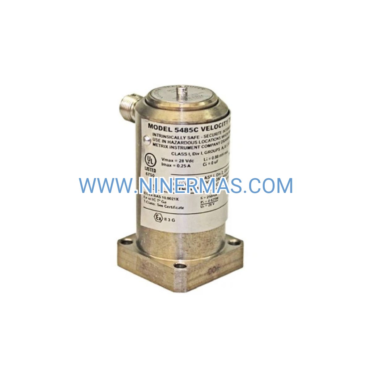
The GE 329A3529P001 Velocity Transducer is an industrial-grade vibration monitoring sensor designed for aeroderivative gas turbine applications. Through precision velocity measurement technology and rugged stainless steel construction, it delivers real-time machinery health diagnostics for critical rotating equipment in power generation, oil & gas, and marine propulsion systems.
Specifically engineered for GE LM1600, LM2500, and LM6000 gas turbine platforms, this velocity sensor addresses common operational challenges including bearing degradation, rotor imbalance, shaft misalignment, and mechanical looseness. It serves design engineers, maintenance teams, turbine operators, and system integrators who require reliable condition monitoring data to prevent catastrophic failures and optimize asset performance.
With proven field reliability across thousands of installations worldwide, the 329A3529P001 velocity transducer features IP67 environmental protection, wide frequency response (10-1000 Hz), and seamless integration with GE Speedtronic Mark V and Mark VIe control platforms. Contact our application engineers for customized vibration monitoring solutions, technical specifications, and competitive quotations tailored to your turbine configuration.
Core Features & Technical Advantages
Precision Velocity Measurement Technology
Utilizes moving-coil electromagnetic principle with 100 mV/in/s sensitivity (±5% tolerance) to capture vibration velocity signals across 10-1000 Hz bandwidth. This wide frequency range enables detection of both low-speed bearing defects and high-frequency gear mesh issues, providing comprehensive machinery diagnostics without signal conditioning requirements.
Extreme Environment Durability
Housed in hermetically sealed 316 stainless steel construction rated for -40°C to +121°C continuous operation. IP67 ingress protection shields internal components from moisture, dust, and corrosive atmospheres common in offshore platforms, desert installations, and coastal power plants. Electromagnetic shielding prevents interference from adjacent high-voltage equipment.
Direct OEM Compatibility
Factory-calibrated for plug-and-play installation on GE LM-series turbine bearing housings with standard 1/4-28 UNF mounting threads. 2-pin MS connector ensures secure electrical termination compatible with existing Mark V/VIe vibration input modules, eliminating costly wiring modifications during sensor replacement or system upgrades.
Maintenance-Free Operation
Solid-state velocity sensing element contains no wearing parts or consumables, delivering 10+ years of continuous service life in typical turbine applications. Self-generating output signal requires no external power supply, reducing installation complexity and improving system reliability compared to accelerometer-based alternatives.
Multi-Point Monitoring Capability
Supports simultaneous deployment of multiple sensors across turbine bearing locations (compressor, turbine, gearbox) when paired with multi-channel vibration monitoring systems. Enables advanced diagnostic techniques including orbit analysis, phase measurement, and cross-channel correlation for root cause failure analysis.
Typical Application Scenarios
This velocity transducer addresses vibration monitoring requirements across diverse industrial sectors where machinery reliability directly impacts operational safety and profitability:
Power Generation Gas Turbines
Continuous vibration surveillance of combined-cycle power plants, peaking units, and cogeneration facilities utilizing GE LM-series aeroderivative turbines. Integrates with plant DCS systems to provide automated trip protection and trending data for condition-based maintenance scheduling, reducing forced outage rates by 40-60% compared to time-based maintenance strategies.
Oil & Gas Compression Stations
Real-time monitoring of gas pipeline compressor drives and offshore platform power generation turbines operating in harsh environments with temperature extremes, salt spray exposure, and vibration from adjacent equipment. Early detection of bearing wear and rotor unbalance prevents secondary damage to expensive turbine hot section components.
Marine Propulsion & Auxiliary Systems
Shipboard installation on LM2500 marine gas turbines for naval vessels, cruise ships, and LNG carriers where space constraints and shock/vibration specifications demand compact, rugged sensor solutions. Supports compliance with classification society machinery monitoring requirements (ABS, DNV, Lloyd's Register).
Industrial Mechanical Drive Applications
Monitoring of turbine-driven compressors, pumps, and generators in petrochemical plants, refineries, and manufacturing facilities. Velocity data feeds predictive maintenance programs to optimize overhaul intervals, reduce spare parts inventory, and improve overall equipment effectiveness (OEE) metrics.
Technical Parameters & Selection Guide
To ensure optimal sensor performance and compatibility with your turbine monitoring architecture, reference the following specifications during system design and procurement:
| Parameter | Specification | Notes |
|---|---|---|
| Part Number | 329A3529P001 | GE OEM designation |
| Sensor Technology | Velocity Transducer (Moving Coil) | Self-generating, no external power required |
| Frequency Response | 10 - 1000 Hz (±3 dB) | Covers bearing, unbalance, blade pass frequencies |
| Sensitivity | 100 mV/in/s ±5% | Factory calibrated with traceable certificate |
| Operating Temperature | -40°C to +121°C | Continuous duty rating |
| Housing Material | Stainless Steel 316 | Corrosion resistant, non-magnetic |
| Mounting Configuration | 1/4-28 UNF threaded stud | 15-20 lb-ft installation torque recommended |
| Electrical Termination | 2-pin MS connector | MIL-spec environmental sealing |
| Environmental Rating | IP67 (NEMA 6) | Dust-tight, temporary immersion protected |
| Weight | Approximately 1.0 kg | Includes mounting hardware |
| Compatible Turbines | LM1600, LM2500, LM6000 | Consult factory for other GE models |
| Recommended Cable | Shielded twisted pair, 18-22 AWG | Maximum run length 300m (1000 ft) |
Selection Considerations for Your Application
When specifying the GE 329A3529P001 velocity transducer, evaluate these critical factors to ensure proper system integration: turbine model and bearing housing configuration (verify mounting thread compatibility and clearance), ambient temperature profile (consider insulation or cooling for extreme conditions), vibration monitoring system input requirements (confirm voltage sensitivity matching with existing instrumentation), cable routing distance and EMI environment (specify appropriate shielded cable and grounding practices), and maintenance access requirements (plan sensor locations for inspection without turbine shutdown).
For complex installations involving multiple measurement points, custom cable assemblies, or integration with third-party monitoring systems, our application engineering team provides complimentary design review services. Submit your turbine nameplate data, P&ID drawings, and monitoring system specifications to receive tailored sensor recommendations and installation drawings.
System Integration & Monitoring Architecture
GE Speedtronic Mark V Integration
Connect sensor outputs directly to DS200TBQCG1AAA analog termination boards or DS200TCTGG1A turbine control terminal boards within the Mark V control cabinet. Configure vibration alarm setpoints and trip levels through HMI software to establish three-tier protection (alert / danger / emergency shutdown) based on API 670 machinery protection standards.
Mark VIe Control Platform Compatibility
Interface with IS200TVBAH2ABB vibration input terminal boards or IS220PVIBH1A vibration I/O packs for advanced signal processing including overall vibration trending, frequency spectrum analysis, and automated diagnostics. Leverage Mark VIe ToolboxST software for remote monitoring, historical data archiving, and predictive analytics integration.
Third-Party Monitoring System Options
The 329A3529P001 velocity output signal (100 mV/in/s) interfaces seamlessly with Bently Nevada 3500 series monitors, SKF Multilog systems, Emerson AMS machinery health analyzers, and other industry-standard vibration monitoring platforms. Consult equipment manufacturers for specific input module compatibility and scaling parameters.
Wireless & IIoT Connectivity
For retrofit applications or temporary monitoring campaigns, pair velocity transducers with wireless vibration transmitters supporting Modbus TCP, OPC UA, or MQTT protocols. Cloud-based analytics platforms enable remote expert diagnostics and benchmarking against global turbine fleet performance databases.
Delivery, Service & Quality Assurance
Inventory Availability & Lead Times
Standard GE 329A3529P001 velocity transducers ship from stock within 3-5 business days for single-unit orders. Bulk quantities (10+ units) and custom cable assemblies require 2-3 weeks production lead time. Expedited shipping options available for emergency outage support and critical path project schedules.
Comprehensive Warranty Coverage
All sensors include a 12-month manufacturer warranty covering material defects, workmanship issues, and calibration accuracy. Warranty terms encompass free replacement, return shipping, and technical support for troubleshooting installation or performance concerns. Extended warranty programs available for long-term service agreements.
Technical Documentation Package
Each shipment includes factory calibration certificate with traceability to NIST standards, dimensional outline drawing with mounting specifications, electrical connection diagram showing pin assignments and cable requirements, installation instructions with torque values and surface preparation guidelines, and integration notes for common GE control system configurations.
Application Engineering Support
Our technical team provides complimentary pre-sale consultation for sensor selection, mounting location optimization, and system architecture design. Post-installation support includes remote diagnostics assistance, vibration data interpretation, and troubleshooting guidance for alarm conditions or signal quality issues.
Calibration & Repair Services
Factory-authorized calibration services available with ISO/IEC 17025 accredited test procedures. Typical calibration turnaround time is 5-7 business days including sensitivity verification, frequency response testing, and updated certification documentation. Repair services offered for sensors damaged by installation errors or environmental exposure.
Frequently Asked Questions (FAQ)
Q: How does the GE 329A3529P001 velocity transducer integrate with existing Mark V control systems?
A: The sensor connects directly to Mark V analog input modules (DS200TBQCG1AAA or DS200TCTGG1A terminal boards) using standard shielded twisted-pair cable. Configure vibration monitoring parameters through the Mark V HMI software by setting alarm thresholds, enabling trip logic, and defining data logging intervals. No additional signal conditioning required due to sensor's self-generating 100 mV/in/s output matching Mark V input specifications.
Q: What is the maximum number of velocity transducers supported per turbine monitoring system?
A: Standard GE LM-series turbine configurations utilize 4-8 velocity transducers covering critical bearing locations (compressor forward/aft, turbine forward/aft, gearbox input/output). Mark VIe systems support up to 40 vibration channels per controller using modular I/O expansion, enabling comprehensive multi-point monitoring for complex mechanical drive trains or multiple turbine installations.
Q: Can this velocity sensor replace accelerometer-based vibration monitoring systems?
A: Velocity transducers and accelerometers serve complementary roles in machinery diagnostics. The 329A3529P001 excels at detecting low-frequency issues (10-200 Hz) such as unbalance, misalignment, and bearing wear, while accelerometers better capture high-frequency phenomena (>1 kHz) like gear mesh defects and cavitation. For LM-series turbines, GE specifies velocity transducers as the primary protection sensors due to their reliability and direct velocity output matching turbine trip criteria.
Q: What installation environment requirements must be met for optimal sensor performance?
A: Mount sensors on clean, flat bearing housing surfaces with maximum 0.002" surface roughness. Ensure mounting location experiences representative vibration (avoid nodal points or structural resonances). Maintain ambient temperature within -40°C to +121°C range; for extreme conditions, consider thermal barriers or cooling jackets. Route sensor cables in dedicated conduit separated from high-voltage power cables to minimize electromagnetic interference. Apply anti-seize compound to mounting threads for high-temperature applications above 80°C.
Q: Does the sensor support remote condition monitoring and predictive analytics platforms?
A: Yes, when interfaced with modern vibration monitoring systems featuring Ethernet connectivity (Bently Nevada Orbit 60, Emerson AMS, SKF @ptitude), velocity data streams to cloud-based analytics platforms via OPC UA or Modbus TCP protocols. These systems apply machine learning algorithms to historical vibration trends, enabling automated fault detection, remaining useful life predictions, and fleet-wide performance benchmarking for optimized maintenance planning.
Q: What calibration interval is recommended to maintain measurement accuracy?
A: GE recommends factory recalibration every 3-5 years for sensors in continuous service, or following any mechanical impact, exposure to temperatures exceeding rated limits, or observed drift in baseline vibration readings. Field verification using portable vibration calibrators should be performed annually to confirm sensor sensitivity remains within ±10% of nameplate specification. Maintain calibration records for regulatory compliance and warranty validation.
Q: Are replacement sensors backward compatible with legacy turbine installations from the 1990s?
A: The 329A3529P001 maintains form-fit-function compatibility with earlier GE velocity transducer generations used on LM-series turbines manufactured since 1985. Verify mounting thread specification (1/4-28 UNF standard) and electrical connector type (2-pin MS) match existing installation. Consult turbine serial number and control system revision to confirm compatibility; our technical team provides cross-reference support for obsolete part numbers.
Request Technical Consultation & Quotation
To receive customized vibration monitoring solutions, competitive pricing, and application engineering support for your GE LM-series turbine installation, please provide the following project details:
- Turbine Configuration: Model designation (LM1600/LM2500/LM6000), serial number, control system type (Mark V/VIe)
- Application Environment: Industry sector, installation location (indoor/outdoor/marine), ambient temperature range
- Monitoring Requirements: Number of measurement points, existing vibration system (if any), integration with DCS/SCADA
- Project Timeline: Required delivery date, installation schedule, commissioning support needs
- Quantity & Services: Sensor quantity, cable assemblies, calibration certificates, extended warranty options
Our application engineers respond within 24 hours with tailored recommendations, technical drawings, and comprehensive quotations including sensor hardware, accessories, and optional field service support.
© 2026 NINERMAS COMPANY LIMITED. All rights reserved.
Original Source: https://ninermas.com
Contact: sale@ninermas.com | +0086 187 5021 5667


Contact Info
-
Address:22 / F, South Wo Hang building, 148 Wing Lok Street, Sheung Wan, Western District, Hong Kong
-
Phone:+8618750215667
-
Email: