Original Industrial Spare Part
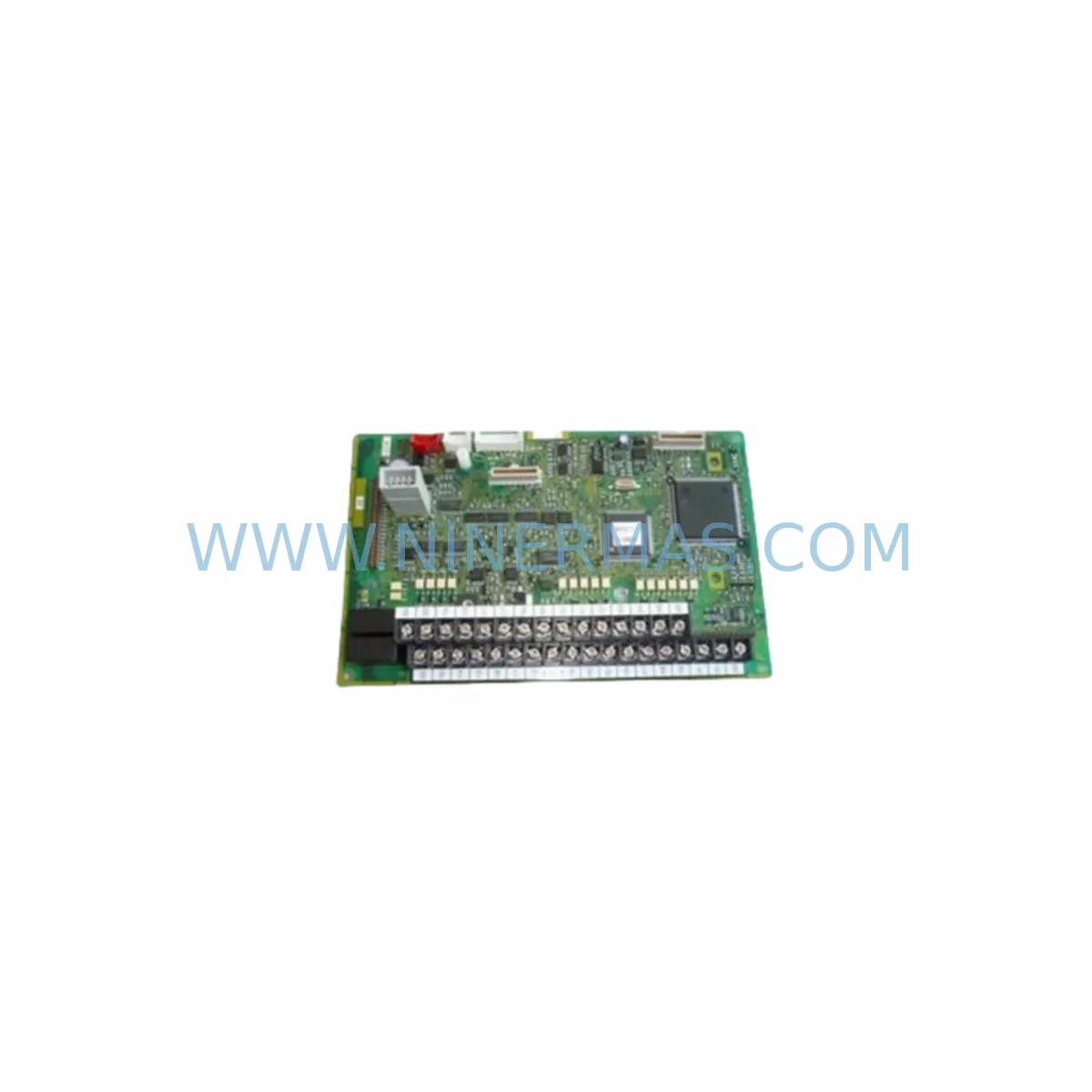
FUJI EP-3364B-CA-Z2 Service-Ready Spare Part for Industrial Maintenance
Verify the part, confirm the platform family, and move straight into quotation with the right commercial details.
RFQ Ready
- SKUEP-3364B-CA-Z2
- CategoryPLC & Industrial Automation Modules
- BrandFUJI
- SupportAvailability, lead time, condition, and shipping coordination
How Buyers Usually Use This Page
- Confirm the exact part number and platform family before sending the quote request.
- Use direct email when quantity, condition, and destination are already defined internally.
- Switch to the broader brand or category archive when you need alternates nearby.
Series Navigation
Move through the most common platform families behind this part.
Product RFQ
Send this part directly for quotation.
Include quantity, required condition, destination country, and target delivery timing. Current reference: FUJI EP-3364B-CA-Z2 Service-Ready Spare Part for Industrial Maintenance with SKU EP-3364B-CA-Z2.
FUJI EP-3364B-CA-Z2 Service-Ready Spare Part for Industrial Maintenance
The FUJI EP-3364B-CA-Z2 is an original inverter control board designed for FRENIC series variable frequency drives (VFDs). In industrial environments where unplanned downtime translates directly into production loss, having a verified, pre-tested control board on the shelf is a fundamental risk mitigation strategy. This board governs the core logic of the FRENIC drive — managing PWM signal generation, gate drive coordination, fault detection, and communication interface handling. When the EP-3364B-CA-Z2 fails or degrades, the entire drive becomes inoperable, making rapid spare part availability critical to restoring motor control and resuming production.
Sourced as an original FUJI Electric component, the EP-3364B-CA-Z2 is suited for maintenance engineers managing aging FRENIC drive installations across compressor stations, pump control panels, conveyor systems, HVAC units, and general-purpose motor control cabinets. Whether you are executing a planned annual overhaul, responding to an emergency fault alarm, or building a strategic spare parts buffer for a multi-drive facility, this control board provides the compatibility and reliability required for mission-critical applications.
Spare Maintenance Table
| Part Number | EP-3364B-CA-Z2 |
| Brand | FUJI Electric |
| Series Compatibility | FRENIC Series Variable Frequency Drives (VFDs) |
| Component Type | Inverter Control Board (Main PCB) |
| Origin | Japan |
| Board Function | PWM control, gate drive logic, fault detection, I/O interface, communication handling |
| Applicable Drive Ratings | Refer to FRENIC series drive nameplate and technical documentation for exact frame match |
| Installation Environment | Indoor industrial control cabinet; IP20 or better enclosure recommended |
| Operating Temperature | -10°C to +50°C (standard FRENIC drive operating range) |
| Humidity | 5% to 95% RH, non-condensing |
| Maintenance Recommendation | Replace upon fault code recurrence, visible PCB damage, or drive failure to initialize |
| Pre-Shipment Testing | Yes — functional verification performed before dispatch |
| Warranty | 12 Months |
| Supply Continuity | Long-term stock maintained for legacy FRENIC drive support |
Maintenance Planning for Continuous Operation
Replacing the EP-3364B-CA-Z2 control board is rarely an isolated task. Experienced maintenance engineers understand that a control board failure in a FRENIC drive is often symptomatic of broader electrical stress within the drive cabinet or the upstream power supply circuit. A structured inspection protocol should accompany any control board replacement to prevent repeat failures and ensure the drive returns to stable operation.
Begin with the DC bus capacitor bank — electrolytic capacitors in FRENIC drives age with thermal cycling and should be measured for capacitance and ESR before the replacement board is powered. A degraded capacitor bank will stress the new control board immediately upon startup. Inspect the IGBT power module (such as the FUJI 6MBP series or equivalent FRENIC frame module) for gate-emitter leakage and collector-emitter saturation voltage; a failing power module is a common root cause of control board damage through overcurrent events.
Check the gate drive board or driver PCB that interfaces between the EP-3364B-CA-Z2 and the IGBT module. Burnt traces, cracked solder joints, or failed optocouplers on the gate driver will destroy a replacement control board within hours of commissioning. Inspect the power supply board (SMPS section) that provides the +5V, +15V, and ±15V rails to the control board — voltage ripple or dropout on these rails is a frequent cause of unexplained control board faults and communication errors.
For drives with active fieldbus communication, verify the communication option card (PROFIBUS, DeviceNet, Modbus RTU, or CC-Link depending on site configuration) is seated correctly and that the communication cable shielding is intact. A damaged option card can generate bus errors that are misdiagnosed as control board failures. Similarly, inspect the I/O terminal board for correct wiring, terminal torque, and signal integrity — loose connections on analog input channels (frequency reference, PID feedback) or digital input terminals (run/stop, fault reset) can cause erratic drive behavior that mimics a faulty control board.
Review the keypad/operator panel (FUJI TP-E1 or equivalent FRENIC series panel) and its connection cable for continuity. A failed panel connection can prevent parameter upload/download during commissioning of the replacement board. If the site uses a remote monitoring system or SCADA interface, confirm that the RS-485 or Ethernet communication link is re-established after board replacement and that drive parameters are reloaded from a saved backup. Always verify the input line reactor or EMC filter upstream of the drive for signs of overheating or insulation breakdown, as these components protect the drive from line-side transients that can damage control electronics.
For facilities maintaining a structured spare parts inventory, the EP-3364B-CA-Z2 should be stocked alongside the gate driver PCB, the SMPS power supply board, and at least one IGBT module matched to the drive frame size. This three-component buffer covers the majority of FRENIC drive failure scenarios and enables same-shift restoration in most cases.
Site Replacement Workflow
Step 1 — Isolation and lockout: Isolate the drive from the AC supply and apply LOTO (Lockout/Tagout) procedure. Wait a minimum of 10 minutes for DC bus capacitors to discharge below 30V DC before opening the drive enclosure. Verify with a calibrated DC voltmeter across the P(+) and N(-) bus terminals.
Step 2 — Parameter backup: If the existing drive is still partially functional, upload all parameters to the keypad or a PC tool (FUJI Frenic Loader or equivalent) before removing the control board. Parameter loss during board swap is a common cause of extended commissioning time.
Step 3 — Board removal: Document all ribbon cable, flat flex cable, and connector positions with photographs before disconnection. The EP-3364B-CA-Z2 connects to the gate driver board, power supply board, I/O terminal board, and operator panel via multiple connectors — incorrect reconnection will cause immediate faults or damage.
Step 4 — Board installation: Install the replacement EP-3364B-CA-Z2 using ESD precautions. Reconnect all cables in the documented sequence. Confirm that all board-to-board connectors are fully seated and latched.
Step 5 — Parameter restore and commissioning: Restore saved parameters from backup. Verify motor nameplate data, acceleration/deceleration ramp settings, and protection thresholds before enabling the drive. Perform a no-load test run before reconnecting the mechanical load.
Step 6 — System verification: Confirm communication link restoration (fieldbus, SCADA), verify analog and digital I/O signal integrity, and log the replacement in the site maintenance record. Monitor the drive for the first 24 hours of operation for any recurrence of fault codes.
This workflow minimizes total downtime and reduces the risk of repeat failure. For legacy FRENIC installations where original documentation is unavailable, our technical team can assist with parameter template guidance based on drive model and application type.
Spare Parts Support FAQ
Q: Is the EP-3364B-CA-Z2 compatible with all FRENIC series drives?
A: The EP-3364B-CA-Z2 is specific to certain FRENIC series drive frames and power ratings. Compatibility depends on the drive model number and production date code. Please provide your drive nameplate data (model, capacity, and serial number) when ordering to confirm exact fitment before shipment.
Q: What pre-shipment testing is performed on this control board?
A: Each EP-3364B-CA-Z2 undergoes functional verification prior to dispatch, including power-on initialization checks and communication interface testing where applicable. A test report is available upon request. This process is part of our standard quality control protocol and supports the 12-month warranty coverage.
Q: How long is the warranty and what does it cover?
A: All EP-3364B-CA-Z2 units supplied by NINERMAS carry a 12-month warranty from the date of shipment. The warranty covers manufacturing defects and functional failure under normal operating conditions. It does not cover damage resulting from incorrect installation, overvoltage events, or operation outside the specified environmental parameters.
Q: Can you support long-term or repeat supply for multi-site maintenance programs?
A: Yes. NINERMAS maintains dedicated stock of FRENIC series spare components to support ongoing maintenance programs, annual shutdown schedules, and emergency call-out requirements. We can provide scheduled delivery agreements and reserved inventory allocation for customers managing multiple drive installations or extended service contracts.
| Product Series | Other series |
|---|
Catalog Continuation
More FUJI modules in the catalog.
Use the brand lane to compare nearby part numbers, platform-adjacent modules, and other inquiry-ready listings before sending your final RFQ.
Catalog Continuation
Alternative parts within PLC & Industrial Automation Modules.
Stay inside the same system family when you need substitutes, adjacent modules, or a broader shortlist for procurement review.
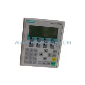
SKU: 6AV6641-0CA01-0AX1
Siemens 6AV6641-0CA01-0AX1 Service-Ready Spare Part for Industrial Maintenance
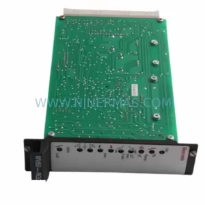
SKU: VT-VSPA1-1-11
Rexroth VT-VSPA1-1-11 Retrofit-Compatible Valve Amplifier