Original Industrial Spare Part
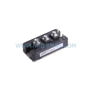
Fuji 2DI75Z-120 Retrofit-Compatible Power Module Legacy Systems
Verify the part, confirm the platform family, and move straight into quotation with the right commercial details.
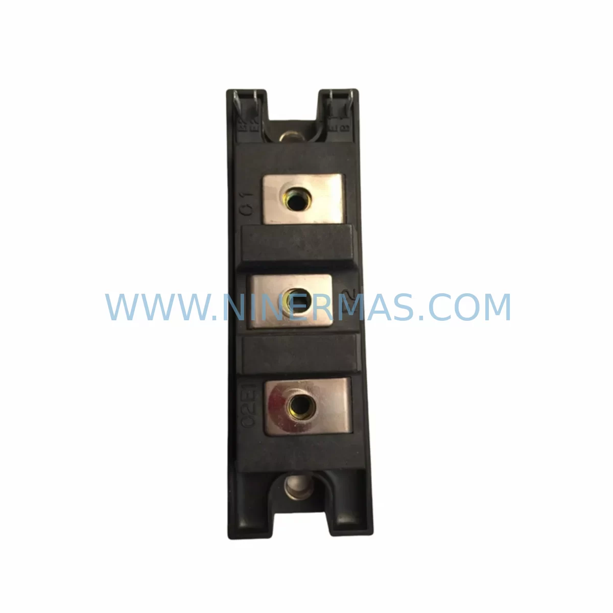
RFQ Ready
- SKU2DI75Z-120
- CategoryPLC & Industrial Automation Modules
- BrandFuji Electric
- SupportAvailability, lead time, condition, and shipping coordination
How Buyers Usually Use This Page
- Confirm the exact part number and platform family before sending the quote request.
- Use direct email when quantity, condition, and destination are already defined internally.
- Switch to the broader brand or category archive when you need alternates nearby.
Series Navigation
Move through the most common platform families behind this part.
Product RFQ
Send this part directly for quotation.
Include quantity, required condition, destination country, and target delivery timing. Current reference: Fuji 2DI75Z-120 Retrofit-Compatible Power Module Legacy Systems with SKU 2DI75Z-120.
Fuji 2DI75Z-120 Retrofit-Compatible Power Module for Legacy Systems
The Fuji Electric 2DI75Z-120 is a dual IGBT power module rated at 75A / 1200V, originally designed for high-performance inverter drives, servo amplifiers, and industrial AC motor control systems. As legacy automation platforms approach end-of-life and original spare parts become increasingly scarce, the 2DI75Z-120 remains one of the most sought-after retrofit components for engineers tasked with extending the operational life of existing control cabinets without committing to a full system replacement.
NINERMAS maintains verified stock of the 2DI75Z-120 sourced from qualified industrial supply channels. Each unit undergoes pre-shipment functional testing and is backed by a 12-month warranty, giving maintenance teams the confidence to proceed with planned or emergency retrofits on production lines where downtime carries significant cost.
Upgrade Compatibility Table
| Parameter | 2DI75Z-120 (Legacy) | Retrofit Notes |
|---|---|---|
| Collector Current (Ic) | 75A | Verify drive’s rated current does not exceed module rating under peak load |
| Collector-Emitter Voltage (Vces) | 1200V | Suitable for 690V AC bus systems; confirm DC link voltage headroom |
| Package Type | Dual IGBT Module (2DI series) | Direct footprint match within 2DI series; verify mounting hole pattern |
| Gate Drive Voltage | +15V / -8V (typical) | Confirm existing gate driver board (e.g., EXB841 or equivalent) output levels |
| Thermal Interface | Flat base, M5 mounting screws | Apply fresh thermal compound; torque to manufacturer specification |
| Communication Compatibility | N/A (power stage only) | No protocol changes required; upper control logic unaffected |
| Replacement Suggestion | 2DI75Z-120 → 2MBI75S-120 (if footprint permits) | 2MBI series offers improved switching characteristics for newer drives |
| Commissioning Focus | Gate signal integrity, thermal resistance, DC bus balance | Oscilloscope verification of gate waveform recommended before full load |
| 12-Month Warranty | All units supplied by NINERMAS carry a 12-month warranty from date of shipment | |
Retrofit Planning for Existing Automation Systems
When planning a retrofit around the 2DI75Z-120, the scope of work extends well beyond the module itself. Maintenance engineers must evaluate the entire power conversion stack to ensure a reliable, long-term outcome.
Power Capacity and DC Bus Verification: Before installation, confirm that the existing power supply module — often a dedicated rectifier or capacitor bank assembly within the control cabinet — can sustain the required DC link voltage under the new module’s switching characteristics. In many legacy inverter platforms, the DC bus capacitors have aged significantly and may need replacement alongside the IGBT module to prevent premature failure.
Gate Driver Compatibility: The 2DI75Z-120 requires a gate driver capable of delivering the correct turn-on and turn-off voltages. Many legacy systems use dedicated gate driver boards such as the EXB841, which was widely deployed in Fuji-based inverter platforms. Engineers should inspect the gate driver for signs of degradation — particularly the bootstrap capacitors and optocoupler isolation stages — and replace if necessary. In some upgrade paths, the 2MBI75S-120 or 2MBI100VA-120-50 may be considered as functional successors if the gate driver board supports the updated switching parameters.
Terminal Wiring and Backplane Interface: The 2DI series module uses a standard terminal layout for the collector, emitter, and gate connections. When replacing a failed unit, document the existing wiring before disconnection. Pay particular attention to the snubber circuit connections and any shared emitter terminals that interface with the drive’s current sensing circuitry. In rack-mounted systems, the backplane connector alignment must be verified to prevent intermittent contact faults after reassembly.
Module Address and Program Compatibility: Since the 2DI75Z-120 is a power stage component, it does not carry any programmable address or firmware. However, the surrounding control platform — which may include a legacy PLC, motion controller, or dedicated inverter CPU board — must be verified for compatibility with the restored power stage. If the drive’s control board has also been replaced or upgraded, confirm that the PWM output timing and dead-time settings are appropriate for the 2DI75Z-120’s switching speed.
I/O Expansion and Signal Isolation: In systems where the inverter interfaces with a broader automation network — for example, a Mitsubishi MELSEC or Siemens S5/S7 platform — the I/O expansion modules and signal isolators between the drive and the PLC must be inspected. Signal isolators in the analog speed reference circuit can introduce offset errors if their calibration has drifted, leading to unexpected motor behavior after the power module replacement.
HMI Screen and Communication Link Verification: After completing the hardware replacement, verify that the HMI display — whether a standalone operator panel or a SCADA-connected touchscreen — correctly reflects the drive’s operating status. In legacy systems using RS-485 or proprietary serial protocols, the communication link between the drive and the HMI should be tested under load to confirm that fault codes and speed feedback are transmitted accurately.
Installation Space and Thermal Management: The 2DI75Z-120 requires adequate heatsink contact and airflow. In densely packed control cabinets, verify that adjacent components — including the 2DI50Z-120 or 2DI100Z-120 modules in multi-axis configurations — do not obstruct airflow paths. Thermal imaging of the cabinet interior after a short run-in period is recommended to identify any hotspots before returning the system to full production duty.
Related Components in the Retrofit Path: A complete retrofit often involves sourcing several components simultaneously. Engineers working on Fuji-based inverter platforms frequently require the 2DI150Z-120 for higher-current axes, the 6MBP75RA120 as an IPM-based alternative where space permits, and the A50L-0001-0259 for Fanuc-specification drives that share the same power module footprint. Programming cables and parameter backup tools should also be prepared before beginning any power stage replacement to protect existing motor tuning data.
Downtime Control During System Migration
Minimizing production downtime during a power module replacement requires disciplined pre-planning. The following approach has proven effective across a wide range of legacy inverter retrofit projects:
Pre-Shutdown Preparation: Before taking the system offline, back up all drive parameters using the manufacturer’s programming tool or a compatible parameter cloning device. For Fuji inverter platforms, this typically involves connecting a programming cable to the drive’s RS-232 or USB port and saving the full parameter set to a laptop or handheld programmer. Confirm that the backup file is readable before proceeding.
Controlled Shutdown and Isolation: Follow the drive manufacturer’s recommended shutdown sequence. Allow the DC bus capacitors to fully discharge — typically indicated by the charge LED extinguishing — before opening the cabinet and touching any internal components. Use a calibrated multimeter to verify that the DC bus voltage has dropped to a safe level before beginning module removal.
Module Replacement and Inspection: Remove the failed 2DI75Z-120 carefully, noting the orientation and torque marks on the mounting hardware. Inspect the heatsink surface for contamination or corrosion and clean thoroughly before installing the replacement unit. Apply a thin, even layer of thermal interface material and torque the mounting screws to the specified value to ensure optimal thermal contact.
Recommissioning and Load Testing: After reassembly, power the system up in a controlled manner — ideally with the motor uncoupled from the load — and verify gate signal integrity using an oscilloscope. Gradually increase the load while monitoring module temperature, DC bus voltage, and output current. Confirm that all HMI displays and PLC feedback signals are operating correctly before returning the system to automatic production mode.
Documentation and Spare Parts Inventory: Record the replacement date, module serial number, and any observations from the commissioning process. Maintaining a small buffer stock of the 2DI75Z-120 — or its nearest modern equivalent, the 7MBR75VB120-50 — is strongly recommended for production-critical applications where a second failure would result in extended downtime.
Retrofit Support FAQ
Q1: Is the 2DI75Z-120 a direct drop-in replacement for other modules in the 2DI series?
A: The 2DI75Z-120 shares the same package footprint as other modules in the Fuji 2DI series, including the 2DI50Z-120 and 2DI100Z-120. However, the current rating differs, so engineers must confirm that the 75A rating is appropriate for the specific drive application before substituting. In some cases, the 2MBI75S-120 may serve as a functional upgrade if the gate driver and mounting arrangement are compatible.
Q2: What pre-shipment testing does NINERMAS perform on the 2DI75Z-120?
A: Each 2DI75Z-120 unit supplied by NINERMAS undergoes functional verification including gate-emitter threshold testing, collector-emitter leakage measurement, and visual inspection for physical damage. Units that do not meet specification are quarantined and not shipped. A test report is available upon request for critical applications.
Q3: How should I verify wiring compatibility before installing the replacement module?
A: Photograph or sketch the existing terminal connections before disconnecting any wiring. Verify that the gate resistor values on the drive’s gate driver board are appropriate for the 2DI75Z-120’s input capacitance. If the original gate driver board used with the failed module was an EXB841 or similar discrete driver, confirm that its output voltage levels and propagation delay are within the new module’s specification.
Q4: What is the warranty coverage and lead time for the 2DI75Z-120?
A: NINERMAS provides a 12-month warranty on all 2DI75Z-120 units from the date of shipment, covering manufacturing defects and functional failures under normal operating conditions. For in-stock units, standard lead time is 3–7 business days for international shipments. For urgent requirements, expedited shipping options are available — contact our sales team for current availability and lead time confirmation.
| Product Series | Other series |
|---|
Catalog Continuation
More Fuji Electric modules in the catalog.
Use the brand lane to compare nearby part numbers, platform-adjacent modules, and other inquiry-ready listings before sending your final RFQ.
Catalog Continuation
Alternative parts within PLC & Industrial Automation Modules.
Stay inside the same system family when you need substitutes, adjacent modules, or a broader shortlist for procurement review.