Original Industrial Spare Part
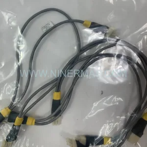
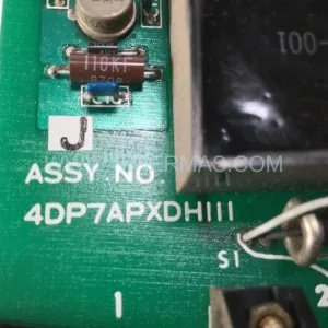
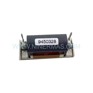
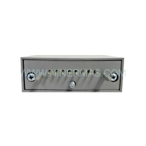
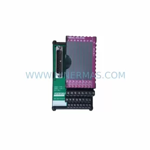
Foxboro P0400DA FBM01 Retrofit-Compatible Safety I/O Module
Verify the part, confirm the platform family, and move straight into quotation with the right commercial details.
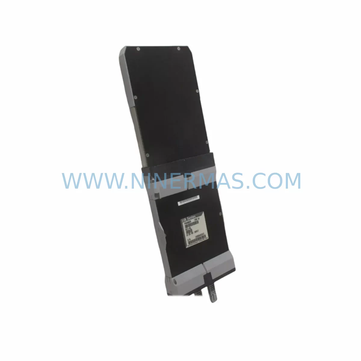
RFQ Ready
- SKUP0400DA FBM01
- CategorySIS Safety & Redundancy Systems
- BrandFOXBORO
- SupportAvailability, lead time, condition, and shipping coordination
How Buyers Usually Use This Page
- Confirm the exact part number and platform family before sending the quote request.
- Use direct email when quantity, condition, and destination are already defined internally.
- Switch to the broader brand or category archive when you need alternates nearby.
Series Navigation
Move through the most common platform families behind this part.
Product RFQ
Send this part directly for quotation.
Include quantity, required condition, destination country, and target delivery timing. Current reference: Foxboro P0400DA FBM01 Retrofit-Compatible Safety I/O Module with SKU P0400DA FBM01.
Foxboro P0400DA FBM01 Retrofit-Compatible Safety I/O Module for Legacy DCS Systems
The Foxboro P0400DA FBM01 is a ruggedized field bus module designed for safety-critical I/O applications within the Foxboro I/A Series Distributed Control System (DCS) platform. As legacy automation infrastructure ages and OEM support windows close, the P0400DA FBM01 has become a cornerstone spare part for engineers managing plant-wide control system continuity, brownfield retrofits, and phased migration programs. NINERMAS maintains verified stock of this module with full functional testing and a 12-month warranty, supporting procurement teams that require reliable lead times and documented traceability.
Whether you are replacing a failed module on an operating unit, building a retrofit kit for a scheduled turnaround, or executing a control system upgrade from an obsolete I/A Series rack configuration, the P0400DA FBM01 delivers the electrical and protocol compatibility your engineering team needs without forcing a full platform migration.
Upgrade Compatibility Table
| Parameter | P0400DA FBM01 Specification | Retrofit / Replacement Notes |
|---|---|---|
| Module Type | Ruggedized Field Bus Module (FBM), Safety I/O | Direct replacement for same FBM01 slot in I/A Series baseplate |
| Platform Compatibility | Foxboro I/A Series DCS | Compatible with existing FCP270, FCM10E, and CP60 controller environments |
| Communication Interface | Nodebus / Fieldbus (I/A Series proprietary) | No protocol converter required for same-platform swap; verify Nodebus address assignment |
| Backplane / Rack Interface | Standard I/A Series FBM baseplate connector | Confirm baseplate model (P0914YE, P0914YF, or equivalent); check for bent pins before insertion |
| Power Supply Requirement | Supplied via baseplate from DCS power bus | Verify P0922VW or equivalent power supply capacity before hot-swap; check bus voltage under load |
| Terminal Wiring | Field termination via marshalling cabinet or FBM termination assembly | Retain existing termination assembly; no rewiring required for direct swap |
| Module Address | Configured via I/A Series system software (IA_ADMIN / FoxCAE) | Restore module address from ICC backup or re-enter via FoxCAE after replacement |
| Installation Space | Standard FBM single-slot form factor | No enclosure modification required; fits existing control cabinet cutout |
| Commissioning Tool | FoxCAE / IA_ADMIN workstation | Confirm software version compatibility; update module firmware if required |
| Warranty | 12-Month Warranty — All units tested prior to shipment. Functional verification report available on request. | |
Retrofit Planning for Existing Automation Systems
Successful integration of the Foxboro P0400DA FBM01 into an existing I/A Series installation requires a structured pre-replacement assessment. Engineers should begin by auditing the current rack configuration, identifying the baseplate model in use — typically a P0914YE or P0914YF FBM baseplate — and confirming that the slot designated for the replacement module is electrically isolated before removal of the failed unit.
Power supply capacity is a critical checkpoint. The P0922VW or equivalent I/A Series DCS power supply module must be verified for adequate headroom, particularly in high-density racks where multiple FBMs share a common bus. A bus voltage measurement under full load should be documented before and after module insertion to confirm stable operation.
Terminal wiring for the P0400DA FBM01 is routed through the existing marshalling cabinet or a dedicated FBM termination assembly. In most brownfield scenarios, the termination assembly remains in place and no field rewiring is necessary, significantly reducing installation time and the risk of wiring errors. Engineers should inspect terminal blocks for corrosion or loose connections before re-energizing the circuit.
Module address configuration is performed through the FoxCAE engineering workstation or the IA_ADMIN system management interface. If an ICC (Integrated Control Configurator) backup is available, the module address and I/O channel assignments can be restored directly from the configuration archive. Where no backup exists, the address must be re-entered manually and verified against the loop drawings and P&ID documentation.
For plants executing a broader control system upgrade — for example, migrating from an older FCP270 field control processor to a newer FCP280 or transitioning I/O subsystems to a Foxboro Evo architecture — the P0400DA FBM01 can serve as a bridging component, maintaining field I/O continuity while the controller layer is upgraded in stages. This phased approach avoids the need for a full cutover and allows engineering teams to validate each segment of the migration independently.
Communication link integrity should be confirmed on the Nodebus segment serving the replacement module. Use the I/A Series diagnostic tools to verify that the module appears on the bus, that all configured I/O channels are reporting correctly, and that no address conflicts exist with adjacent modules such as the FBM02, FBM04, or FBM207 types that may share the same baseplate or Nodebus segment.
Where the retrofit scope extends to HMI integration, confirm that the Foxboro SCADA or third-party HMI display pages referencing the replaced module’s tag names are updated to reflect any channel reassignments. In most direct-swap scenarios, tag names and display bindings remain unchanged, but this should be verified during the commissioning walkthrough before returning the unit to automatic control.
For projects involving I/O expansion alongside the module replacement — for example, adding new measurement points to an existing loop — consider whether additional FBM termination assemblies, signal isolators, or programming cables (such as the P0972VE FoxCAE cable) are required to complete the installation. NINERMAS can supply these ancillary components as part of a consolidated retrofit kit, reducing procurement lead time and simplifying site logistics.
Downtime Control During System Migration
Minimizing unplanned downtime is the primary operational constraint in any live-plant FBM replacement. The P0400DA FBM01 supports hot-swap capability within the I/A Series architecture, provided the baseplate power bus is within specification and the replacement module has been pre-configured with the correct address and firmware version before insertion. Pre-staging the module on the bench — loading the address, verifying firmware, and confirming channel configuration against the ICC backup — reduces on-site installation time to under 30 minutes in most cases.
To protect existing program logic during the swap, the FCP controller should be placed in a controlled state before the module is removed. The I/A Series platform supports bumpless transfer for most I/O types, allowing the controller to maintain its last known output state while the FBM is offline. Engineers should confirm the fallback behavior for each channel — particularly for safety-critical outputs — and coordinate with the operations team to ensure that manual overrides or field bypasses are in place for the duration of the replacement window.
Post-installation, a structured commissioning sequence should be followed: confirm module presence on the Nodebus diagnostic display, verify channel-by-channel I/O readings against field instruments, check alarm and interlock logic for correct response, and document the completed replacement in the plant maintenance management system. Where a SIL-rated safety function is involved, a partial stroke test or proof test may be required before the loop is returned to automatic service, in accordance with the site’s functional safety management plan.
For turnaround-driven replacements where the plant is already offline, the window should be used to inspect adjacent components — including the FBM baseplate, Nodebus terminator, and power supply module — for signs of wear or impending failure. Replacing marginal components during a planned outage is significantly less costly than responding to an unplanned trip caused by a secondary failure shortly after the primary repair.
Retrofit Support FAQ
Q1: Is the Foxboro P0400DA FBM01 a direct drop-in replacement for the original module?
Yes. The P0400DA FBM01 is a form-fit-function replacement for the original Foxboro FBM01 module in the I/A Series platform. It uses the same baseplate connector, the same Nodebus communication interface, and the same channel configuration structure. No hardware modifications to the rack or termination assembly are required for a direct swap. Module address and firmware should be verified before insertion.
Q2: What pre-shipment testing does NINERMAS perform on the P0400DA FBM01?
All units supplied by NINERMAS undergo functional verification testing prior to shipment, including power-on self-test, I/O channel continuity checks, and communication interface validation. A test report is available on request. Each unit is covered by a 12-month warranty from the date of shipment, with direct technical support from the NINERMAS engineering team.
Q3: Can the P0400DA FBM01 be used in a mixed-generation I/A Series rack alongside newer FBM types?
Yes, in most configurations. The I/A Series platform is designed to support mixed FBM generations within the same rack and on the same Nodebus segment. However, engineers should confirm that the FCP controller firmware version supports the P0400DA FBM01 module type and that no address conflicts exist with other modules on the segment. Consult the I/A Series hardware compatibility matrix or contact NINERMAS for application-specific guidance.
Q4: What is the typical lead time and stock availability for the P0400DA FBM01?
NINERMAS maintains standing inventory of the Foxboro P0400DA FBM01 to support urgent replacement and planned procurement programs. Standard lead time for in-stock units is 3–5 business days for international shipment. For long-term spare parts programs or multi-unit procurement, NINERMAS offers stock commitment agreements to guarantee availability over a 12–24 month horizon. Contact sale@ninermas.com or call +0086 187 5021 5667 for current stock status and pricing.
| Product Series | I/A Series |
|---|---|
| Country of Origin | FR |
Catalog Continuation
More FOXBORO modules in the catalog.
Use the brand lane to compare nearby part numbers, platform-adjacent modules, and other inquiry-ready listings before sending your final RFQ.
SKU: P0961BS-OD P0961BS-0D
Foxboro P0961BS-OD Safety-Reliable Bus Connector
SKU: FBM203 P0916AE0C P0916AEOC
Foxboro FBM203 P0916AE0C Service-Ready Spare Part
Catalog Continuation
Alternative parts within SIS Safety & Redundancy Systems.
Stay inside the same system family when you need substitutes, adjacent modules, or a broader shortlist for procurement review.