Original Industrial Spare Part
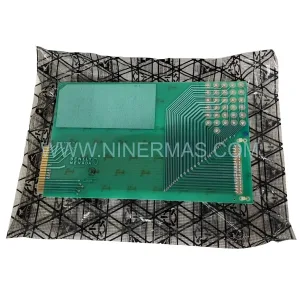
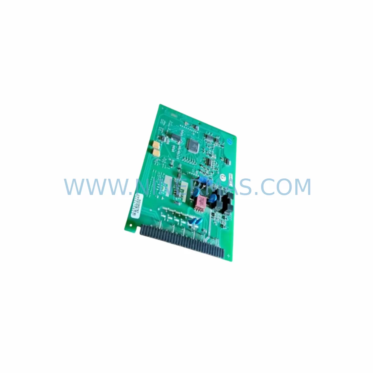
Endress+Hauser AG319100-0200C/D Retrofit PCB for Legacy Systems
Verify the part, confirm the platform family, and move straight into quotation with the right commercial details.
RFQ Ready
- SKUAG319100-0200C AG319100-0200D
- CategoryPLC & Industrial Automation Modules
- BrandEndress+Hauser
- SupportAvailability, lead time, condition, and shipping coordination
How Buyers Usually Use This Page
- Confirm the exact part number and platform family before sending the quote request.
- Use direct email when quantity, condition, and destination are already defined internally.
- Switch to the broader brand or category archive when you need alternates nearby.
Series Navigation
Move through the most common platform families behind this part.
Product RFQ
Send this part directly for quotation.
Include quantity, required condition, destination country, and target delivery timing. Current reference: Endress+Hauser AG319100-0200C/D Retrofit PCB for Legacy Systems with SKU AG319100-0200C AG319100-0200D.
Endress+Hauser AG319100-0200C/D Retrofit-Compatible PCB for Legacy Automation Systems
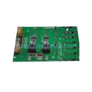
The Endress+Hauser AG319100-0200C and AG319100-0200D are industrial-grade printed circuit boards (PCBs) designed for process instrumentation and control system applications. As original spare parts, these boards serve as direct replacements within legacy Endress+Hauser analyzer and transmitter platforms, enabling plant engineers and maintenance teams to extend the operational life of existing installations without committing to a full system overhaul.
In today’s industrial environment, many facilities continue to operate aging automation infrastructure built around platforms that have since been discontinued or phased out of active production. The AG319100-0200C and AG319100-0200D boards address this challenge directly — providing a verified, retrofit-compatible solution that preserves existing wiring configurations, backplane interfaces, and communication links while restoring full system functionality.
Whether you are managing a brownfield upgrade, responding to an unplanned board failure, or executing a planned spare-parts lifecycle program, these PCBs are stocked and available for immediate dispatch with a 12-month warranty from NINERMAS COMPANY LIMITED.
Upgrade Compatibility Table
| Parameter | AG319100-0200C | AG319100-0200D | Retrofit Notes |
|---|---|---|---|
| Form Factor | Standard PCB module | Standard PCB module | Confirm backplane slot dimensions before installation |
| Interface / Connector | Original Endress+Hauser edge connector | Original Endress+Hauser edge connector | No adapter required for same-generation chassis |
| Communication Compatibility | HART / PROFIBUS (platform-dependent) | HART / PROFIBUS (platform-dependent) | Verify protocol stack version with existing host system |
| Power Supply Requirement | 24 VDC nominal (verify with system BOM) | 24 VDC nominal (verify with system BOM) | Check rail capacity before hot-swap or cold-swap |
| Installation Method | Direct board swap | Direct board swap | ESD precautions required; power down before replacement |
| Replacement Scope | Like-for-like replacement of -0200C revision | Like-for-like replacement of -0200D revision | Confirm firmware revision compatibility with host analyzer |
| Commissioning Requirement | Minimal — restore saved parameters via FieldCare or PDM | Minimal — restore saved parameters via FieldCare or PDM | Back up device parameters before board removal |
| Warranty | 12 Months — NINERMAS COMPANY LIMITED | Covers manufacturing defects; excludes physical damage | |
Retrofit Planning for Existing Automation Systems
Successful integration of the AG319100-0200C or AG319100-0200D into an existing control architecture requires a structured pre-installation review. The following considerations apply to most brownfield retrofit scenarios involving Endress+Hauser process instrumentation platforms.
Power Supply Capacity Verification: Before installing the replacement PCB, confirm that the existing 24 VDC power supply rail — typically sourced from a dedicated instrument power supply module within the control cabinet — has sufficient headroom to support the board’s inrush and steady-state current draw. In multi-drop HART loops or PROFIBUS PA segments, the cumulative load of connected field devices must be recalculated if any topology changes are made during the retrofit.
Terminal Wiring and I/O Mapping: The AG319100-0200C and AG319100-0200D boards retain the original terminal block layout of their respective analyzer platforms. However, engineers should cross-reference the existing wiring diagram against the replacement board’s terminal assignment sheet to confirm signal polarity, shielding continuity, and ground reference points. In installations where analog I/O modules or digital I/O expansion cards are connected to the same backplane, the I/O address map must be preserved to avoid conflicts with the host PLC or DCS configuration.
Backplane Interface and Module Addressing: In rack-based Endress+Hauser systems, each PCB module occupies a defined slot address on the backplane. When replacing the AG319100-0200C or AG319100-0200D, the slot position must remain unchanged unless a full rack reconfiguration is planned. Any change in module address will require corresponding updates in the host system’s hardware configuration — including any associated PROFIBUS DP master configuration files or GSD-based device descriptions.
Program Logic and HMI Screen Compatibility: In systems where the analyzer output feeds into a SIMATIC S7 or similar PLC platform via PROFIBUS DP, the data block structure and process variable mapping must be validated after board replacement. HMI screens built on WinCC, FactoryTalk View, or equivalent SCADA platforms should be tested against live process values to confirm that tag assignments, alarm thresholds, and trend displays remain accurate. If the replacement board introduces a firmware revision change, re-parameterization via Endress+Hauser FieldCare or the legacy COMMUWIN II interface tool may be required.
Communication Link Integrity: For PROFIBUS PA or HART multi-drop installations, the communication segment should be tested with a handheld communicator or segment checker after board installation. Confirm that the device address is correctly assigned and that the host system recognizes the replacement board without generating configuration mismatch alarms. In FOUNDATION Fieldbus installations, re-registration of the device in the linking device or HSE host may be necessary.
Installation Space and Mechanical Fit: Verify that the replacement PCB fits within the available installation envelope of the analyzer housing or control cabinet sub-rack. In compact panel-mount installations, cable routing and connector clearance should be confirmed before final assembly. If the existing installation uses a DIN rail-mounted power supply or signal isolator adjacent to the analyzer module, ensure that the replacement board does not obstruct ventilation slots or create thermal interference.
Related components commonly required during the same retrofit window include: Endress+Hauser RMA42 transmitter modules, CPM223 controller boards, CUM223 communication modules, power supply boards from the Liquiline CM442 platform, PROFIBUS DP communication cards, analog input/output expansion modules, FXA291 Fieldgate communication adapters, and DIN rail terminal blocks for signal rewiring. In some installations, a replacement programming cable or USB service interface adapter is also required to complete device parameterization after board swap.
Downtime Control During System Migration
Minimizing production downtime during a PCB board replacement is a primary concern for maintenance engineers operating in continuous-process environments. The following approach is recommended for AG319100-0200C and AG319100-0200D replacement projects.
Pre-Shutdown Preparation: Before taking the analyzer or transmitter offline, export all device parameters using FieldCare, DeviceCare, or the applicable Endress+Hauser configuration tool. Save the parameter set to a secure location — this file will be used to restore the device configuration after the replacement board is installed. If the system is connected to a DCS or PLC, coordinate with the control room to place the affected loop in manual mode and confirm that any interlock or safety function associated with the measurement point is bypassed or inhibited per the site’s management of change procedure.
Board Swap Execution: Power down the analyzer or instrument housing before removing the defective PCB. Follow ESD handling procedures throughout. Install the AG319100-0200C or AG319100-0200D replacement board into the correct slot, reconnect all terminal wiring per the saved wiring diagram, and restore power. The device should initialize and begin self-diagnostics within the normal boot sequence.
Recommissioning and Verification: Restore the saved parameter set via the configuration tool. Verify that all process variables — flow, level, temperature, conductivity, or pH depending on the analyzer type — are reading correctly against known reference values or a portable calibration standard. Confirm that HART or PROFIBUS communication is re-established with the host system and that no active diagnostic alarms remain. Return the loop to automatic mode only after all verification steps are complete.
Documentation and Handover: Record the replacement board’s serial number, installation date, and firmware version in the site’s maintenance management system. Update the as-built wiring diagram if any terminal changes were made during the retrofit. Retain the defective board for failure analysis if required by the site’s quality or reliability program.
With proper pre-planning, a like-for-like AG319100-0200C or AG319100-0200D board replacement can typically be completed within a single planned maintenance window, with total loop downtime measured in hours rather than days.
Retrofit Support FAQ
Q1: Is the AG319100-0200D a direct drop-in replacement for the AG319100-0200C?
The -0200C and -0200D are revision variants of the same base board design. In most installations they are functionally interchangeable, but you should confirm firmware compatibility with your specific analyzer platform before substituting one revision for the other. Contact our technical team with your analyzer model and serial number for a definitive compatibility assessment.
Q2: What pre-shipment testing is performed on these boards?
All AG319100-0200C and AG319100-0200D boards supplied by NINERMAS are inspected and function-tested prior to dispatch. Each unit is verified for electrical continuity, component integrity, and basic operational parameters. A test report is available upon request. All boards are covered by a 12-month warranty against manufacturing defects from the date of shipment.
Q3: Do you hold stock for immediate dispatch?
Yes. NINERMAS maintains inventory of both the AG319100-0200C and AG319100-0200D to support urgent breakdown and planned maintenance requirements. Standard lead time for in-stock units is 3–7 business days depending on destination. For time-critical shutdowns, expedited dispatch options are available — contact sale@ninermas.com or call +0086 187 5021 5667 to confirm availability and arrange priority shipping.
Q4: What information should I provide when ordering to ensure I receive the correct board revision?
Please provide the full analyzer model number, the existing board part number (AG319100-0200C or AG319100-0200D), the firmware version currently installed if known, and the application context (e.g., PROFIBUS PA segment, HART loop, standalone analyzer). This allows our team to confirm the correct revision and advise on any commissioning considerations specific to your installation.
| Product Series | Legacy |
|---|---|
| Country of Origin | CH |
Catalog Continuation
More Endress+Hauser modules in the catalog.
Use the brand lane to compare nearby part numbers, platform-adjacent modules, and other inquiry-ready listings before sending your final RFQ.
Catalog Continuation
Alternative parts within PLC & Industrial Automation Modules.
Stay inside the same system family when you need substitutes, adjacent modules, or a broader shortlist for procurement review.