Original Industrial Spare Part
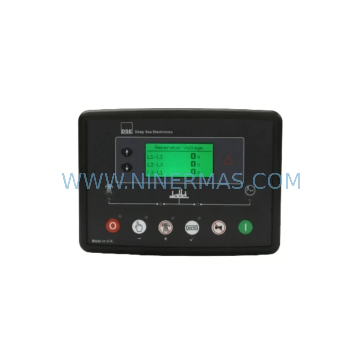
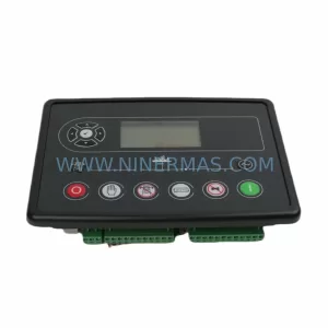
DSE DSE6120 MKII Retrofit-Compatible AMF Control for Legacy Systems
Verify the part, confirm the platform family, and move straight into quotation with the right commercial details.
RFQ Ready
- SKUDSE6120 MKII
- CategoryPLC & Industrial Automation Modules
- BrandDeep Sea Electronics
- SupportAvailability, lead time, condition, and shipping coordination
How Buyers Usually Use This Page
- Confirm the exact part number and platform family before sending the quote request.
- Use direct email when quantity, condition, and destination are already defined internally.
- Switch to the broader brand or category archive when you need alternates nearby.
Series Navigation
Move through the most common platform families behind this part.
Product RFQ
Send this part directly for quotation.
Include quantity, required condition, destination country, and target delivery timing. Current reference: DSE DSE6120 MKII Retrofit-Compatible AMF Control for Legacy Systems with SKU DSE6120 MKII.
DSE DSE6120 MKII Retrofit-Compatible AMF Control for Legacy Systems
The Deep Sea Electronics DSE6120 MKII is a ruggedized Automatic Mains Failure (AMF) control module engineered for seamless integration into existing generator control panels and legacy automation enclosures. Whether you are replacing an end-of-life controller, upgrading a deteriorating control cabinet, or restoring a critical standby power system, the DSE6120 MKII delivers the reliability, compatibility, and field-proven performance that industrial maintenance engineers and system integrators demand.
Designed as a direct retrofit solution for older DSE-series controllers and third-party AMF modules, the DSE6120 MKII supports a wide range of genset configurations from 50 Hz and 60 Hz single-phase and three-phase systems. Its compact DIN-rail and panel-mount form factor ensures it fits within the original control cabinet footprint, minimizing the need for enclosure modifications and reducing overall retrofit labor costs.
Upgrade Compatibility Table
| Parameter | DSE6120 MKII | Retrofit Notes |
|---|---|---|
| Supply Voltage | 8–35 V DC | Verify existing panel DC bus; compatible with most 12 V and 24 V battery systems |
| Mains Sensing Input | Up to 333 V AC (L-N) | Confirm transformer tap or direct sensing wiring from legacy terminal block |
| Output Relays | 8 configurable outputs | Map legacy relay assignments to new output configuration via DSE Configuration Suite PC software |
| Digital Inputs | 8 configurable inputs | Re-terminate existing field wiring; label each input before disconnection |
| Communication Interface | RS-232 / USB (via DSE890 adapter) | For SCADA or BMS integration, pair with DSE890 Mk2 PC Interface or DSE855 Ethernet module |
| Panel Cutout | 180 × 160 mm | Measure existing cutout; adapter plates available for larger legacy openings |
| Ingress Protection | IP65 (front face) | Suitable for outdoor and harsh-environment enclosures without additional sealing |
| Replacement Compatibility | DSE6010, DSE6020, DSE6110, DSE6120 Mk1 | Direct terminal-for-terminal replacement in most installations; verify wiring diagram revision |
| Commissioning Tool | DSE Configuration Suite | Free download; supports parameter cloning from previous DSE modules where backup file exists |
| Warranty | 12 Months | Covered from date of dispatch; includes DOA exchange and technical support |
Retrofit Planning for Existing Automation Systems
A successful retrofit begins well before the first terminal is loosened. When planning the replacement of an aging AMF controller with the DSE6120 MKII, the first step is a thorough audit of the existing control cabinet. Document every wire termination on the outgoing controller, photograph the terminal block layout, and cross-reference the original wiring diagram against the DSE6120 MKII terminal assignment sheet. Pay particular attention to the mains sensing voltage input wiring — many legacy panels use a step-down transformer to reduce mains voltage to a safe sensing level, and this transformer must be verified to be within the DSE6120 MKII’s input range before energizing the new module.
Power supply integrity is equally critical. The DSE6120 MKII draws its operating power from the generator battery bus, typically 12 V DC or 24 V DC. Before installation, measure the battery bus voltage under load and confirm that the existing battery charger module — often a DSE9480 or equivalent float charger — is functioning correctly and maintaining the bus within the 8–35 V DC operating window. A weak or failing charger is a common cause of nuisance shutdowns after retrofit and should be replaced proactively as part of the upgrade scope.
For panels that previously relied on a DSE6010 or DSE6020 controller, the terminal layout of the DSE6120 MKII is largely compatible, but engineers should verify the assignment of configurable digital inputs and outputs. The DSE6120 MKII’s eight configurable outputs provide greater flexibility than earlier models, allowing functions such as fuel solenoid control, pre-heat activation, and remote start signaling to be reassigned without hardware changes. Use the DSE Configuration Suite software to load a baseline configuration before installation, reducing on-site programming time significantly.
Where the legacy system included a DSE5110 MKII or DSE5120 MKII synchronizing module in a parallel generation application, the migration path to the DSE6120 MKII requires careful review of the inter-module communication wiring. The DSE6120 MKII is designed for single-set AMF applications; parallel applications should instead consider the DSE8610 MKII or DSE8620 MKII load-sharing controllers. Confirming the application architecture early prevents costly rework during commissioning.
I/O expansion requirements should also be assessed during the planning phase. If the legacy system used external relay expansion boards or signal isolators to interface with third-party sensors or SCADA systems, verify that the DSE6120 MKII’s native I/O count is sufficient or plan for the addition of a DSE890 Mk2 PC Interface Module or a DSE855 Ethernet Communications Module to maintain remote monitoring capability. For installations with Modbus RTU or Modbus TCP requirements, the DSE855 provides a straightforward migration path without requiring changes to the upstream SCADA or building management system configuration.
HMI considerations are often overlooked in retrofit projects. If the existing panel included a dedicated operator interface panel or a third-party HMI screen displaying genset parameters via serial communication, the communication protocol and baud rate settings must be reconfigured to match the DSE6120 MKII’s RS-232 output. In many cases, the HMI screen graphics will require updating to reflect the new parameter register map. Budget time for this during the commissioning phase and confirm with the HMI supplier whether a firmware update is available to support DSE6120 MKII register addressing.
Backplane and rack-mount installations in larger switchgear assemblies may require the use of a DSE124 Relay Output Expansion Module to replicate the full relay output count of the legacy controller. Confirm rack dimensions and DIN rail availability within the existing enclosure before ordering ancillary modules, and ensure that the combined current draw of all modules does not exceed the rating of the existing DC distribution fuse or MCB protecting the control circuit.
Downtime Control During System Migration
Minimizing unplanned downtime is the primary concern for any facility undertaking an AMF controller retrofit. The DSE6120 MKII’s compatibility with the DSE Configuration Suite allows engineers to pre-program the replacement module on the bench using a laptop before the scheduled maintenance window begins. Where a configuration backup file exists from the previous DSE controller, parameters including start delay timers, mains failure thresholds, and alarm setpoints can be imported directly, eliminating manual re-entry and reducing the risk of transcription errors.
During the physical swap, adopt a structured terminal-by-terminal transfer approach rather than disconnecting all wiring simultaneously. Use numbered cable ties or adhesive labels to identify each conductor before removal, and work from a printed copy of the legacy wiring diagram alongside the DSE6120 MKII terminal assignment sheet. This method allows a single engineer to complete the rewiring safely and accurately within a typical two-to-four-hour maintenance window, depending on panel complexity.
Before restoring mains power and initiating the first automatic test, perform a static verification of all output relay assignments using the DSE Configuration Suite’s manual override function. This allows each output — fuel solenoid, starter motor, cooling fan, and alarm outputs — to be exercised individually without starting the generator, confirming correct wiring before a live test. Once static verification is complete, perform a supervised manual start followed by a simulated mains failure test to confirm correct AMF sequencing, transfer timing, and mains restoration behavior.
For critical facilities where any interruption to standby power availability is unacceptable, consider staging the retrofit during a planned maintenance outage when the protected load can be temporarily supplied from an alternative source. Coordinate with the facility’s electrical safety officer and ensure that all isolation procedures comply with local electrical safety regulations before beginning work. Document the completed retrofit with updated as-built drawings and a commissioning test record, and retain these documents alongside the unit’s 12-month warranty certificate for future reference.
Retrofit Support FAQ
Q: Is the DSE6120 MKII a direct drop-in replacement for the DSE6120 Mk1?
A: In the majority of installations, yes. The terminal layout and panel cutout dimensions are compatible with the original DSE6120 Mk1. However, engineers should review the DSE6120 MKII wiring diagram to confirm that any site-specific modifications made to the original installation are accounted for before completing the swap.
Q: Can I clone the configuration from my old DSE controller to the DSE6120 MKII?
A: If a configuration backup file was saved from the previous DSE module using the DSE Configuration Suite, many parameters can be imported directly. Note that some parameters may require manual verification after import, particularly output relay assignments and communication settings, as register maps may differ between firmware versions.
Q: What pre-shipment testing is performed on the DSE6120 MKII?
A: Each unit undergoes functional testing prior to dispatch, including power-on verification, input/output relay operation checks, and display functionality confirmation. Units are supplied with a test record and are covered by a 12-month warranty from the date of dispatch. Dead-on-arrival (DOA) units are exchanged promptly subject to inspection.
Q: What is the typical lead time and stock availability?
A: NINERMAS maintains stock of the DSE6120 MKII to support urgent retrofit and breakdown replacement requirements. Standard orders are dispatched within 1–3 business days. For large-quantity or project-based orders, contact our sales team at sale@ninermas.com or +0086 187 5021 5667 to confirm availability and lead time.
| Product Series | Legacy |
|---|---|
| Country of Origin | GB |
Catalog Continuation
More Deep Sea Electronics modules in the catalog.
Use the brand lane to compare nearby part numbers, platform-adjacent modules, and other inquiry-ready listings before sending your final RFQ.
Catalog Continuation
Alternative parts within PLC & Industrial Automation Modules.
Stay inside the same system family when you need substitutes, adjacent modules, or a broader shortlist for procurement review.
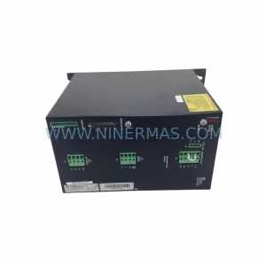
SKU: SCE906A2-002-01 SCE906A200201
Pacific Scientific SCE906A2-002-01 Retrofit Servo Amplifier
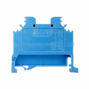
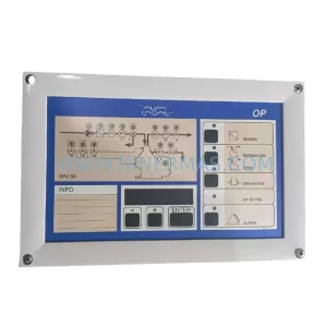
SKU: EPC500 3183062451
Alfa Laval EPC500 3183062451 Service-Ready Spare Part