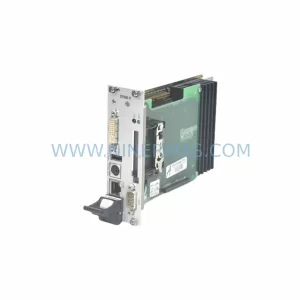
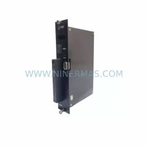
Original Industrial Spare Part
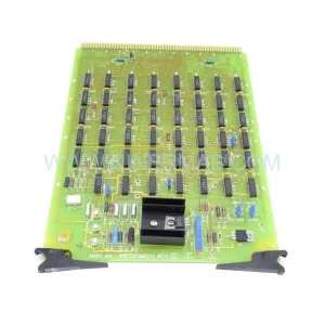
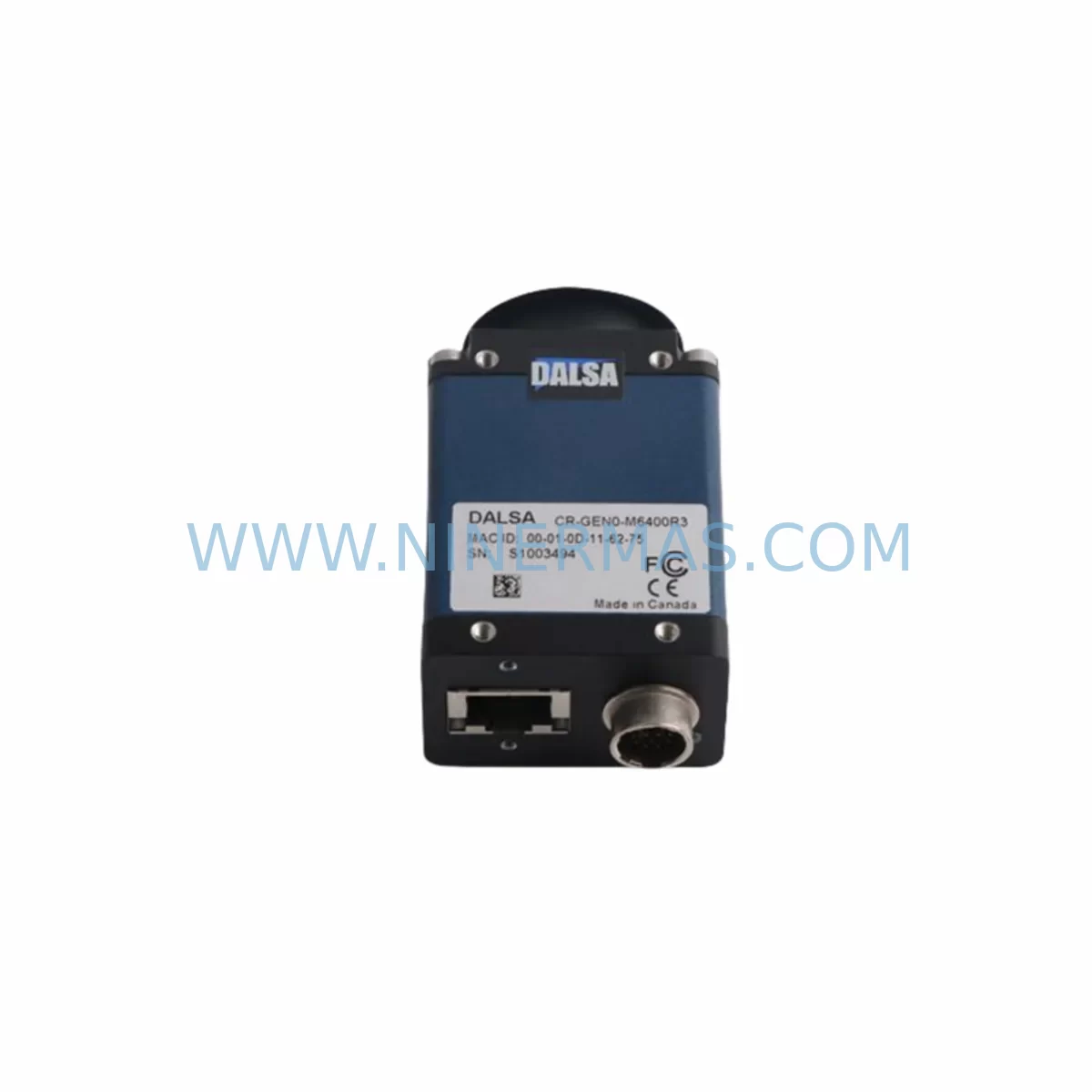
DALSA CR-GEN0-M6400R3 Retrofit-Compatible Vision Module
Verify the part, confirm the platform family, and move straight into quotation with the right commercial details.
RFQ Ready
- SKUCR-GEN0-M6400R3
- CategoryPLC & Industrial Automation Modules
- BrandDALSA
- SupportAvailability, lead time, condition, and shipping coordination
How Buyers Usually Use This Page
- Confirm the exact part number and platform family before sending the quote request.
- Use direct email when quantity, condition, and destination are already defined internally.
- Switch to the broader brand or category archive when you need alternates nearby.
Series Navigation
Move through the most common platform families behind this part.
Product RFQ
Send this part directly for quotation.
Include quantity, required condition, destination country, and target delivery timing. Current reference: DALSA CR-GEN0-M6400R3 Retrofit-Compatible Vision Module with SKU CR-GEN0-M6400R3.
DALSA CR-GEN0-M6400R3 Retrofit-Compatible Vision Module: Seamless Legacy System Upgrade
The DALSA CR-GEN0-M6400R3 is a ruggedized machine vision module engineered for demanding industrial environments where legacy imaging systems must be modernized without disrupting production continuity. As a retrofit-compatible replacement within the DALSA Genie and CR-series vision platform ecosystem, this module addresses the growing challenge of sourcing discontinued vision components for aging automated inspection lines, robotic guidance systems, and quality control stations. Whether you are upgrading a legacy conveyor inspection cell, replacing an end-of-life frame grabber assembly, or migrating from an older GigE Vision or Camera Link interface to a more current architecture, the CR-GEN0-M6400R3 provides a reliable, field-proven path forward.
Industrial facilities operating DALSA CR-series vision controllers — including platforms paired with the Sapera LT SDK, Teledyne DALSA Genie Nano, or legacy Coreco Imaging frame grabbers — frequently encounter the challenge of maintaining imaging performance when original modules reach end-of-life. The CR-GEN0-M6400R3 is designed to slot into existing CR-series enclosures and control cabinet vision subsystems with minimal mechanical modification, preserving the original installation footprint and reducing retrofit engineering time. Its ruggedized construction supports operation in environments with elevated vibration, temperature cycling, and particulate contamination — conditions common in automotive stamping plants, semiconductor fabs, food processing lines, and heavy manufacturing cells.
When planning a retrofit around the CR-GEN0-M6400R3, engineers must systematically verify several integration parameters before committing to a cutover. Power supply capacity within the control cabinet is a primary concern: the existing 24 VDC rail must be confirmed to support the module’s inrush and steady-state draw alongside co-located components such as the Cognex In-Sight vision system, SICK safety light curtain controllers, or Keyence laser displacement sensors sharing the same DIN rail power distribution. Terminal block wiring — particularly trigger input lines, strobe output signals, and encoder synchronization connections — must be mapped against the new module’s I/O pinout to identify any adapter harness requirements before the maintenance window begins.
Backplane interface compatibility is another critical checkpoint. Facilities using CR-series rack-mount enclosures should confirm that the module’s connector pitch and locking mechanism align with the existing backplane, especially if the enclosure also houses DALSA Xcelera frame grabber cards or third-party image processing boards. Module addressing — whether via DIP switch, rotary selector, or software configuration through the Sapera Processing library — must be documented and replicated in the replacement unit to avoid address conflicts with other vision nodes on the same network segment.
Program compatibility deserves careful attention during the pre-retrofit audit. Vision inspection recipes developed in DALSA’s iNspect or Sherlock vision software, or in third-party environments such as Cognex VisionPro or Halcon, may reference camera-specific calibration files, lens distortion maps, or pixel format settings tied to the outgoing module. These parameters should be exported, archived, and validated against the CR-GEN0-M6400R3’s imaging characteristics before go-live. HMI screen layouts on Siemens SIMATIC HMI panels or Rockwell PanelView terminals that display live camera feeds or inspection result overlays may require resolution or aspect ratio adjustments if the replacement module outputs a different sensor format.
Communication link integrity across the vision network must be verified end-to-end. If the CR-GEN0-M6400R3 connects to a Rockwell Automation ControlLogix or CompactLogix PLC via EtherNet/IP, the EDS file and I/O tag mapping in Studio 5000 Logix Designer should be reviewed to confirm that inspection result data — pass/fail bits, defect classification codes, and part-present signals — routes correctly to the PLC’s input image table. Similarly, if the vision system communicates with a Siemens S7-1500 or S7-300 controller via PROFINET, the GSDML device description file may need updating to reflect the replacement module’s identity.
Installation space confirmation is a practical prerequisite that is often underestimated. The CR-GEN0-M6400R3’s physical envelope — including connector clearance zones and cable bend radius requirements for Camera Link or GigE Vision cabling — must be measured against the available cabinet depth and adjacent component spacing. In tight retrofit scenarios where the original module was installed alongside Allen-Bradley 1756 I/O modules, Phoenix Contact power supplies, or Weidmüller terminal blocks, a dimensional mock-up or 3D model review can prevent costly rework during the maintenance window.
On-site commissioning of the CR-GEN0-M6400R3 follows a structured sequence: power-on verification, network discovery and IP assignment, camera calibration using a certified calibration target, inspection recipe reload and parameter validation, and finally a production trial run with statistical sampling to confirm detection performance meets the original specification. Downtime during this sequence can be compressed by pre-staging the replacement module on a bench test fixture — using a DALSA Xcelera-CL PX4 or equivalent frame grabber card in a test PC — to validate firmware version compatibility and image quality before the production cutover.
NINERMAS maintains verified inventory of the CR-GEN0-M6400R3 with a 12-month warranty covering manufacturing defects and functional performance. Each unit undergoes outgoing inspection including power-on test, interface verification, and imaging function check before shipment. Lead times and stock levels are confirmed at the time of inquiry, supporting both emergency replacement orders and planned spare parts programs for facilities managing long-term lifecycle commitments on DALSA vision infrastructure.
Upgrade Compatibility Table
| Parameter | Legacy / Outgoing Module | CR-GEN0-M6400R3 (Replacement) | Retrofit Note |
|---|---|---|---|
| Interface Type | Camera Link / Analog | CR-series backplane / GigE Vision compatible | Verify frame grabber card compatibility |
| Power Supply | 24 VDC (legacy rail) | 24 VDC nominal | Confirm rail capacity with co-located loads |
| Mounting / Form Factor | CR-series rack enclosure | CR-series rack enclosure (same footprint) | Check connector clearance and cable bend radius |
| Communication Protocol | EtherNet/IP / PROFINET / RS-232 | EtherNet/IP / PROFINET compatible | Update EDS / GSDML files in PLC project |
| Software / SDK | Sapera LT, iNspect, Sherlock | Sapera LT / Sapera Processing compatible | Re-validate inspection recipes and calibration files |
| Module Addressing | DIP switch / software | Software configurable | Replicate original address to avoid network conflicts |
| HMI Integration | Siemens SIMATIC / Rockwell PanelView | Compatible via standard vision result tags | Adjust resolution/format settings if sensor format differs |
| Environmental Rating | Standard industrial | Ruggedized — vibration, temperature, particulate rated | No additional enclosure modification required |
| Warranty | N/A (end-of-life) | 12-Month Warranty (NINERMAS) | Covers manufacturing defects and functional performance |
Retrofit Planning for Existing Automation Systems
A successful retrofit centered on the CR-GEN0-M6400R3 begins with a comprehensive audit of the existing vision subsystem and its integration points within the broader control architecture. In a typical automotive body-in-white inspection cell, the vision module operates alongside a Rockwell Automation ControlLogix L7x controller, a Cognex DataMan barcode reader for part tracking, and a SICK TiM laser scanner for presence detection — all coordinated through an EtherNet/IP network managed by a Stratix 5700 managed switch. Each of these components has dependencies on the vision module’s trigger timing, inspection cycle time, and result data format that must be preserved through the replacement process.
Terminal block wiring for the CR-GEN0-M6400R3’s I/O connections — including the opto-isolated trigger input, strobe output for LED illumination controllers, and encoder input for motion-synchronized imaging — should be documented using the existing panel drawings before any disconnection. Phoenix Contact or Weidmüller terminal blocks used for signal distribution in the control cabinet should be labeled and photographed to support accurate reconnection. If the original wiring used a custom adapter harness to interface with a non-standard connector on the legacy module, a replacement harness should be fabricated and tested on the bench before the production cutover.
Power distribution within the cabinet deserves particular attention when the CR-GEN0-M6400R3 is installed alongside a SITOP PSU8200 or equivalent DIN rail power supply. The combined load of the vision module, illumination controller, and any co-located Wago 750-series I/O modules or Beckhoff EtherCAT terminals must remain within the power supply’s rated output. A current audit using a clamp meter on the 24 VDC bus before and after module installation confirms that the supply is not operating near its derating threshold.
For facilities migrating from a Camera Link interface to GigE Vision as part of the CR-GEN0-M6400R3 retrofit, the network infrastructure upgrade is a parallel workstream. Replacing the legacy Matrox Radient frame grabber card with a GigE Vision-compatible NIC, configuring jumbo frames on the managed switch, and assigning a static IP address to the replacement module are tasks that can be completed during normal production hours before the maintenance window, minimizing the actual cutover time.
Downtime Control During System Migration
Minimizing unplanned downtime during a CR-GEN0-M6400R3 retrofit requires a structured pre-staging and parallel validation approach. The replacement module should be fully configured, calibrated, and recipe-loaded on a bench test fixture before the production maintenance window opens. Using a DALSA Xcelera-CL PX4 frame grabber or a GigE Vision test NIC in a laptop, engineers can verify that the module’s firmware version is compatible with the production Sapera LT installation, that the inspection recipe produces correct pass/fail results on a set of known-good and known-bad reference parts, and that the module’s network identity and addressing are correctly configured.
During the maintenance window itself, the cutover sequence should be scripted and timed: isolate the vision subsystem from the PLC by forcing the inspection bypass mode in the ControlLogix program, disconnect and label the legacy module’s wiring, install the CR-GEN0-M6400R3, reconnect wiring per the documented terminal assignments, power on and verify network discovery, reload the pre-validated inspection recipe, and release the bypass mode for a supervised production trial. This sequence, when pre-staged correctly, can typically be completed within a two-hour planned maintenance window, preserving the original program logic and HMI screen layouts without modification.
To protect the original program logic during the migration, a full backup of the ControlLogix or S7 PLC project — including all vision result tag mappings, inspection bypass rungs, and HMI screen configurations — should be archived to a secure network location before any changes are made to the control system. This backup serves as the rollback baseline if the retrofit encounters an unexpected compatibility issue that cannot be resolved within the maintenance window, allowing the facility to restore the legacy configuration and reschedule the cutover without extended production loss.
Retrofit Support FAQ
Q: Is the CR-GEN0-M6400R3 a direct drop-in replacement for my existing DALSA CR-series vision module?
A: The CR-GEN0-M6400R3 is designed for CR-series rack enclosures and shares the same mechanical footprint and power requirements as other modules in the CR-GEN family. However, interface connector pinout, sensor format, and firmware version should be verified against your specific legacy module before committing to a direct swap. NINERMAS can provide a compatibility assessment based on your existing module’s part number and installation drawings.
Q: What commissioning steps are required after installing the CR-GEN0-M6400R3?
A: After physical installation and power-on, the commissioning sequence includes network discovery and IP assignment, firmware version verification against the production Sapera LT SDK version, camera calibration using a certified calibration target, inspection recipe reload and parameter validation, and a supervised production trial run with statistical sampling. NINERMAS provides a commissioning checklist with each unit to guide on-site engineers through this process.
Q: Can I use my existing inspection recipes and calibration files with the CR-GEN0-M6400R3?
A: In most cases, inspection recipes developed in Sapera LT, iNspect, or Sherlock can be reloaded on the CR-GEN0-M6400R3 with minor parameter adjustments for sensor format and pixel size differences. Calibration files tied to the legacy module’s specific lens and sensor geometry should be re-validated on the replacement unit using a certified calibration target. NINERMAS recommends a bench validation step before the production cutover to identify any recipe adjustments required.
Q: What does the 12-month warranty cover, and what is the typical lead time?
A: NINERMAS’s 12-month warranty covers manufacturing defects and functional performance failures under normal operating conditions. Each CR-GEN0-M6400R3 unit undergoes outgoing inspection including power-on test, interface verification, and imaging function check before shipment. Lead times vary based on current stock levels and are confirmed at the time of inquiry. For facilities with planned spare parts programs, NINERMAS offers stock reservation arrangements to support long-term lifecycle commitments. Contact sale@ninermas.com or +0086 187 5021 5667 for current availability.
| Product Series | Other series |
|---|
Catalog Continuation
More DALSA modules in the catalog.
Use the brand lane to compare nearby part numbers, platform-adjacent modules, and other inquiry-ready listings before sending your final RFQ.
Catalog Continuation
Alternative parts within PLC & Industrial Automation Modules.
Stay inside the same system family when you need substitutes, adjacent modules, or a broader shortlist for procurement review.