Original Industrial Spare Part
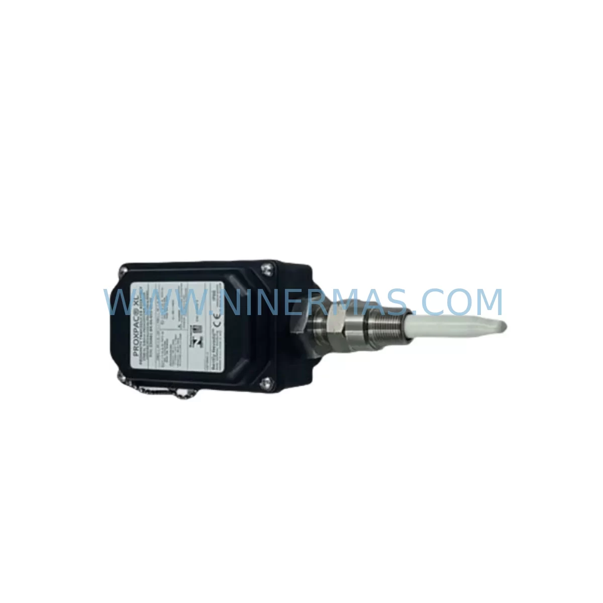
Bently Nevada 330881-28-10-140-00-02 Retrofit Proximity Sensor
Verify the part, confirm the platform family, and move straight into quotation with the right commercial details.
RFQ Ready
- SKU330881-28-10-140-00-02
- CategoryTSI & Rotating Machinery Monitoring
- BrandBently Nevada
- SupportAvailability, lead time, condition, and shipping coordination
How Buyers Usually Use This Page
- Confirm the exact part number and platform family before sending the quote request.
- Use direct email when quantity, condition, and destination are already defined internally.
- Switch to the broader brand or category archive when you need alternates nearby.
Series Navigation
Move through the most common platform families behind this part.
Product RFQ
Send this part directly for quotation.
Include quantity, required condition, destination country, and target delivery timing. Current reference: Bently Nevada 330881-28-10-140-00-02 Retrofit Proximity Sensor with SKU 330881-28-10-140-00-02.
Bently Nevada 330881-28-10-140-00-02 Retrofit Proximity Sensor: Legacy System Compatibility & Smooth Upgrade
The Bently Nevada 330881-28-10-140-00-02 is a proximity sensor module engineered for continuous vibration monitoring in rotating machinery protection systems. As legacy Bently Nevada 3300 Series installations reach end-of-life or face discontinued spare parts availability, this module serves as a direct retrofit-compatible replacement, enabling facilities to extend operational life, restore system integrity, and defer full platform migration without compromising measurement accuracy or safety margins.
Designed to interface with the Bently Nevada 3300 Series rack-based monitoring architecture, the 330881-28-10-140-00-02 supports eddy-current proximity sensing for radial shaft vibration, axial position, and differential expansion measurement. Its 28 mm probe diameter, 10 mm sensing range, and 140 mm extension cable configuration make it a precise fit for turbine, compressor, pump, and gearbox monitoring applications where original OEM specifications must be maintained during retrofit.
Upgrade Compatibility Table
| Parameter | 330881-28-10-140-00-02 (This Unit) | Retrofit Notes |
|---|---|---|
| Series | Bently Nevada 3300 XL / 3300 Series | Compatible with existing 3300 rack infrastructure |
| Probe Diameter | 28 mm | Verify bore clearance before installation |
| Sensing Range | 10 mm | Confirm gap setting per OEM calibration sheet |
| Extension Cable Length | 140 mm | Match to existing conduit routing; avoid splicing |
| Output Signal | -18 VDC (nominal) | Verify driver/monitor input impedance compatibility |
| Communication | Analog (4–20 mA / voltage) | No protocol migration required for 3300 monitors |
| Mounting Interface | Threaded probe tip, standard 3300 bracket | Reuse existing mounting hardware where possible |
| Replacement Path | Direct drop-in for 330881 series variants | Cross-reference suffix codes for cable/range match |
| Commissioning | Gap voltage verification, OK relay check | Use Bently Nevada calibrator or equivalent |
| Warranty | 12-Month Warranty | Covered from date of shipment; includes DOA exchange |
Retrofit Planning for Existing Automation Systems
When integrating the 330881-28-10-140-00-02 into an existing machinery protection system, a structured retrofit plan is essential to avoid unplanned downtime and signal integrity issues. The first step is a full audit of the existing 3300 Series rack configuration, including the 3300/16 monitor cards, 3300/20 power supplies, and any installed 3300/46 or 3300/55 I/O modules. Technicians should document the current channel assignments, alarm setpoints, and OK relay wiring before removing the legacy probe assembly.
Terminal wiring compatibility is a critical checkpoint. The 330881-28-10-140-00-02 uses the standard Bently Nevada three-wire coaxial system — probe, extension cable, and driver — and connects to the monitor card via the existing terminal block. If the original extension cable (such as a 330130 or 330730 series cable) is being reused, inspect the connector pins and shield continuity before reinstallation. Damaged coaxial connectors are a leading cause of false OK relay trips during post-retrofit commissioning.
For facilities running mixed-generation racks that include both 3300 Series monitors and newer 3500 Series modules, the retrofit plan must account for backplane slot compatibility. The 3500/42M and 3500/45 position monitors use a different I/O module form factor and cannot share a backplane with 3300 Series cards. If the upgrade path eventually leads to a 3500 platform migration, plan for a parallel installation phase where both systems run simultaneously to validate alarm thresholds and OK relay logic before cutover.
Power supply capacity is another key consideration. The 3300/20 power supply module supports a defined number of monitor cards per rack. Adding replacement modules or expanding I/O capacity with additional 3300/16 cards may push the rack beyond its rated load. Verify the total current draw against the power supply’s output rating before finalizing the retrofit bill of materials.
HMI screen updates are often overlooked during proximity sensor replacements. If the facility uses a DCS or SCADA system — such as a Honeywell Experion, Emerson DeltaV, or Yokogawa CENTUM — connected to the Bently Nevada rack via a 3500/92 communication gateway or a legacy 3300 Keyphasor interface, verify that the tag names, engineering unit scaling, and alarm limits in the HMI database match the new sensor’s output range. Mismatched scaling is a common source of nuisance alarms in the first weeks after retrofit.
For sites where the 330881-28-10-140-00-02 is replacing a probe in a Keyphasor-referenced measurement loop, confirm that the 3300/25 Keyphasor module is still functional and that the once-per-revolution reference signal is clean. A degraded Keyphasor signal will affect all phase-referenced measurements in the rack, including 1X and 2X vibration vectors displayed on the operator console.
Installation space confirmation is mandatory before ordering. Measure the available probe tip-to-shaft gap, the conduit path for the extension cable, and the clearance around the probe holder. The 140 mm extension cable on this variant is suited for standard bearing housing installations, but tight turbine casings or retrofitted compressor frames may require a custom extension length. Cross-reference the full 330881 suffix matrix to confirm the correct cable length and connector type for your specific application.
Downtime Control During System Migration
Minimizing production downtime during a proximity sensor retrofit requires careful pre-staging and a disciplined cutover sequence. Begin by pre-configuring the replacement 330881-28-10-140-00-02 on the bench: verify the gap voltage output at the nominal 1.0 mm gap using a calibrated driver and a flat steel target. Confirm the OK relay closes within the specified voltage window before the module is brought to site. This bench verification step eliminates the most common cause of extended commissioning time — discovering a faulty unit after the machine is already offline.
During the cutover window, follow a channel-by-channel replacement sequence rather than removing all probes simultaneously. This preserves partial monitoring coverage on the machine and allows the control room operator to maintain visibility on the remaining channels. If the machine cannot be taken fully offline, coordinate with operations to identify which channels are non-critical during the brief replacement window and sequence those first.
Protect the original program logic in the connected DCS or safety system by placing the affected monitor channels in bypass mode before disconnecting the probe. This prevents spurious trip signals from propagating to the emergency shutdown system (ESD) or the distributed control system during the open-circuit condition that exists while the probe is disconnected. Document the bypass activation and restoration in the site’s management of change (MOC) log.
After reinstallation, perform a live gap check with the shaft stationary, then a dynamic check at operating speed to confirm the vibration signal is clean and within the expected amplitude range. Compare the 1X vector reading against the historical baseline stored in the System 1 condition monitoring software or equivalent historian. A significant phase shift or amplitude deviation from baseline may indicate a probe orientation error or a gap setting outside the linear range of the eddy-current system.
With proper pre-staging, a single-channel proximity sensor replacement on a 3300 Series rack can typically be completed within a two-to-four hour maintenance window, including bench verification, installation, gap setting, and signal validation. Having a spare 330881-28-10-140-00-02 in the site’s critical spare parts inventory further reduces risk by eliminating lead time as a variable in unplanned outage scenarios.
Retrofit Support FAQ
Q1: Is the 330881-28-10-140-00-02 a direct replacement for other 330881 suffix variants?
The 330881 series uses a structured suffix system to define probe diameter, sensing range, extension cable length, and connector type. The -28-10-140-00-02 variant specifies a 28 mm probe, 10 mm range, and 140 mm extension cable. It is a direct replacement for units with identical suffix codes. For variants with different cable lengths or connector types, cross-reference the Bently Nevada 330881 selection guide to confirm dimensional and electrical compatibility before ordering.
Q2: What commissioning steps are required after installation?
After mechanical installation, set the probe gap to the target voltage specified on the monitor card channel configuration — typically between -10 VDC and -18 VDC for the linear range. Verify the OK relay status on the 3300/16 monitor card front panel. Confirm the vibration signal is present and noise-free on the System 1 software or the connected DCS historian. Document the as-left gap voltage and alarm setpoints in the site’s maintenance management system (CMMS).
Q3: Does this unit ship with an outgoing quality test report?
Yes. Each 330881-28-10-140-00-02 unit is function-tested prior to shipment. A test report confirming output voltage linearity, OK relay operation, and connector integrity is available upon request. Units are shipped in anti-static packaging with protective caps on the probe tip and connector. All units are covered by a 12-month warranty from the date of shipment, with DOA exchange support.
Q4: What is the stock availability and lead time?
The 330881-28-10-140-00-02 is maintained in stock for immediate shipment. For urgent requirements, same-day dispatch is available for orders confirmed before the daily cutoff. For large-quantity orders or long-term supply agreements, contact our sales team to discuss inventory reservation and scheduled delivery options. All units are sourced from verified supply channels and are subject to incoming inspection before dispatch.
| Product Series | 3308 |
|---|---|
| Country of Origin | US |
Catalog Continuation
More Bently Nevada modules in the catalog.
Use the brand lane to compare nearby part numbers, platform-adjacent modules, and other inquiry-ready listings before sending your final RFQ.
SKU: 330103-00-10-10-11-05
Bently Nevada 330103-00-10-10-11-05 Safety Proximity Transducer
SKU: 330703-000-060-90-02-00
Bently Nevada 330703-000-060-90-02-00 Retrofit Module
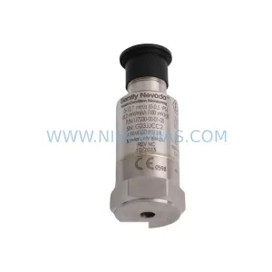
SKU: 177230-00-01-CN 16925-33
Bently Nevada 177230-00-01-CN 16925-33 Service-Ready Spare Part for Industrial Maintenance
Catalog Continuation
Alternative parts within TSI & Rotating Machinery Monitoring.
Stay inside the same system family when you need substitutes, adjacent modules, or a broader shortlist for procurement review.
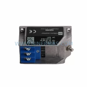
SKU: 204-900-000-011
Vibro-meter 204-900-000-011 Safety-Reliable Vibration Monitor

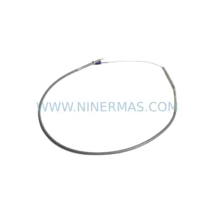
SKU: 330904-00-09-10-02-05/CN
Bently Nevada 330904-00-09-10-02-05/CN Safety-Reliable Vibration Monitor
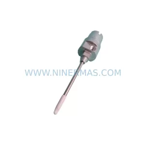
SKU: 21000-28-05-15-024-03-02
Bently Nevada 21000-28-05-15-024-03-02 Retrofit Proximity Probe