Original Industrial Spare Part
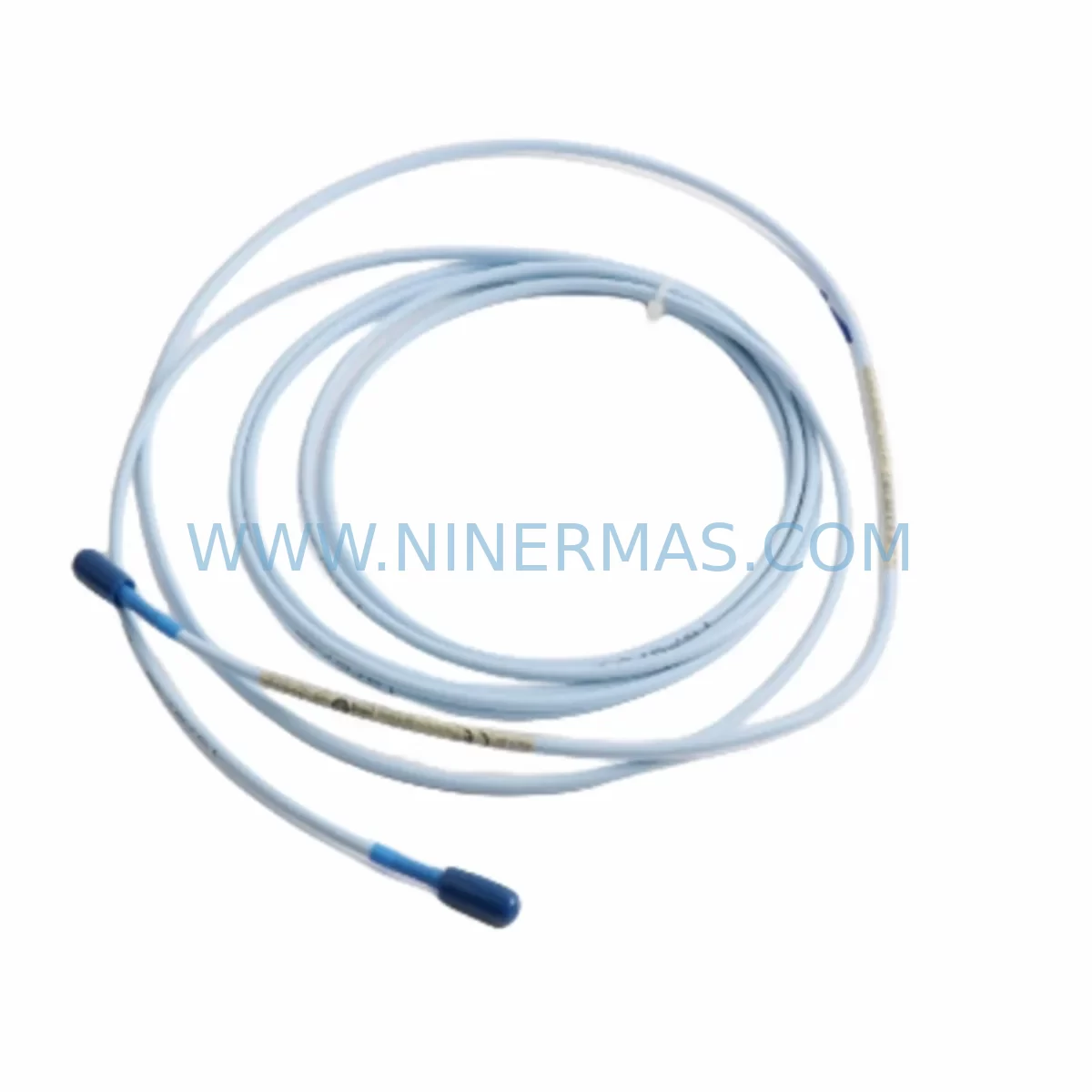
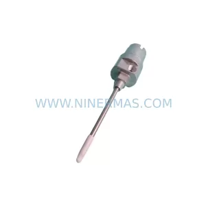
Bently Nevada 330130-035-00-CN Retrofit Proximity Probe
Verify the part, confirm the platform family, and move straight into quotation with the right commercial details.
RFQ Ready
- SKU330130-035-00-CN
- CategoryTSI & Rotating Machinery Monitoring
- BrandBently Nevada
- SupportAvailability, lead time, condition, and shipping coordination
How Buyers Usually Use This Page
- Confirm the exact part number and platform family before sending the quote request.
- Use direct email when quantity, condition, and destination are already defined internally.
- Switch to the broader brand or category archive when you need alternates nearby.
Series Navigation
Move through the most common platform families behind this part.
Product RFQ
Send this part directly for quotation.
Include quantity, required condition, destination country, and target delivery timing. Current reference: Bently Nevada 330130-035-00-CN Retrofit Proximity Probe with SKU 330130-035-00-CN.
Bently Nevada 330130-035-00-CN Retrofit Proximity Probe: Legacy System Compatible Upgrade
The Bently Nevada 330130-035-00-CN is a ruggedized, extension-cable-compatible proximity probe engineered for continuous vibration and position monitoring in rotating machinery. Designed as a direct retrofit replacement for aging 3300 Series and legacy Proximitor® sensor assemblies, this probe enables plant engineers to restore full monitoring capability without redesigning the existing cable routing, conduit layout, or terminal block wiring. Whether you are managing a planned upgrade cycle or responding to an unplanned failure of a discontinued sensor, the 330130-035-00-CN delivers a verified drop-in solution backed by a 12-month warranty and pre-shipment functional testing.
In industrial facilities where machinery protection systems have been in service for 10 to 25 years, the challenge is rarely finding a replacement part — it is finding one that integrates cleanly with the existing infrastructure. The 330130-035-00-CN addresses this directly. Its 5-metre (CN suffix) armored cable length matches the most common field installation distances found in legacy turbine, compressor, and pump monitoring panels, reducing the need for extension splices or conduit rework during the retrofit.
Upgrade Compatibility Table
| Parameter | 330130-035-00-CN Specification | Retrofit / Legacy Comparison |
|---|---|---|
| Probe Tip Diameter | 8 mm (standard 3300 series) | Direct fit for existing 3300 XL 8mm probe holes |
| Cable Length (CN) | 5 metres armored | Matches standard legacy conduit runs; no extension required |
| Output Sensitivity | 7.87 V/mm (200 mV/mil) | Compatible with 3500/40M, 3500/42M, 3500/44M monitor cards |
| Driver / Proximitor | 330180 / 330130 series drivers | Replaces discontinued 330100 and 330105 probe assemblies |
| Supply Voltage | −24 VDC (nominal) | Standard 3300/3500 rack power supply compatible |
| Temperature Range | −35°C to +177°C | Suitable for high-temperature bearing housings and steam environments |
| Communication / Signal | Analog DC voltage output | Direct input to 3500 series I/O modules; no protocol conversion needed |
| Mounting Thread | M10 × 1 mm | Fits existing probe holders; no bracket modification required |
| Installation Clearance | Requires 25 mm radial access | Verify clearance in tight compressor bearing housings before installation |
| Warranty | 12 Months | Covered from date of shipment; includes pre-shipment functional test report |
Retrofit Planning for Existing Automation Systems
Successful integration of the 330130-035-00-CN into a running plant begins well before the probe arrives on site. The first step is a thorough audit of the existing Bently Nevada 3500 rack configuration. Most legacy installations pair the proximity probe with a Bently Nevada 3500/40M Proximitor® Monitor or a 3500/42M Proximitor® Monitor — both of which accept the 200 mV/mil sensitivity output of the 330130 series without any gain adjustment. If the rack includes a 3500/20 Rack Interface Module (RIM), verify that the firmware revision supports the probe’s DC output range before proceeding.
Terminal block wiring is the most common source of commissioning delays during a probe swap. The 330130-035-00-CN uses a standard three-conductor shielded cable (PWR, COM, OUT) that maps directly to the existing terminal assignments on the 3500/40 I/O Module. However, if the original installation used a 330180-51-05 extension cable to bridge the probe to the Proximitor driver, confirm that the extension cable’s connector is undamaged and that the total system cable length does not exceed the 9-metre maximum for the 330130 driver series. Exceeding this limit introduces sensitivity error that will not be caught by a simple continuity check.
For facilities that are simultaneously upgrading their control architecture — for example, migrating from a legacy Bently Nevada 3300 Series rack to a modern 3500 Series rack — the 330130-035-00-CN is the correct probe choice for the new platform. The 3300 Series used a different Proximitor driver (the 330100-90-05 or similar), and those drivers are now discontinued. The 330130-035-00-CN paired with a 330180 Series Proximitor® Sensor provides the equivalent measurement performance on the 3500 platform while maintaining the same probe-tip-to-shaft gap setting (typically 1.0 mm to 1.5 mm for most steel shafts).
Where the retrofit also involves expanding I/O capacity — for instance, adding radial vibration monitoring to a previously unmonitored bearing — the 3500/42M four-channel monitor allows up to four probe channels per card slot, reducing the number of rack slots consumed compared to older single-channel cards. This is particularly valuable in congested control cabinets where backplane space is limited. Confirm backplane slot assignments and module addressing in the Rack Configuration Software (RCS) before powering the rack, as address conflicts between new and existing modules can cause the entire rack to fault on startup.
If the plant’s DCS or safety system communicates with the Bently Nevada rack via Modbus RTU or Ethernet/IP, verify that the 3500/20 RIM’s communication configuration is preserved during the rack modification. A common oversight is resetting the RIM to factory defaults during a firmware update, which clears the node address and baud rate settings and causes a communication loss alarm at the DCS level. Document the existing communication parameters before any firmware work begins.
For HMI integration, if the plant uses a System 1® Evolution condition monitoring platform, the probe replacement does not require any changes to the System 1 database — the channel configuration (gap voltage, alert setpoints, danger setpoints) is stored at the monitor card level and is retained when the probe is swapped. However, after installation, perform a static gap voltage check at the monitor card’s test point to confirm the new probe is gapped correctly before returning the machine to service.
Downtime Control During System Migration
Minimizing unplanned downtime during a proximity probe replacement requires a structured pre-outage preparation process. Begin by obtaining the pre-shipment functional test report for the 330130-035-00-CN — this confirms that the probe’s sensitivity, linearity, and cable integrity have been verified before it leaves the warehouse, eliminating the risk of receiving a defective unit and discovering the fault only after the machine is already shut down.
Before the outage window opens, prepare a printed copy of the existing terminal wiring diagram and photograph the as-found wiring at the junction box and at the monitor card I/O terminal strip. This documentation protects the original program logic and alarm setpoint configuration from accidental modification during the physical swap. If the 3500 rack is connected to a Bently Nevada TDXnet® Data Acquisition System or a third-party historian, place the affected channel in bypass mode at the monitor card before disconnecting the probe to prevent a spurious danger alarm from triggering an automatic machine trip.
The physical probe replacement — removing the old probe from its holder, installing the 330130-035-00-CN, setting the gap, and reconnecting the cable — typically takes 30 to 45 minutes per probe location when the bearing housing is accessible. The subsequent commissioning steps (gap voltage verification, sensitivity check, alarm setpoint confirmation, and bypass removal) add another 15 to 20 minutes. For a four-bearing machine with eight radial probes, plan for a total hands-on time of approximately six to eight hours, excluding any travel time between bearing locations.
After the bypass is removed and the machine is returned to service, monitor the gap voltage and vibration amplitude readings for the first 30 minutes of operation to confirm that the new probe is tracking correctly and that no mechanical interference exists between the probe tip and the shaft. Any sudden change in gap voltage during run-up indicates either an incorrect gap setting or a probe that has shifted in its holder — both of which must be resolved before the machine reaches full operating speed.
Retrofit Support FAQ
Q1: Is the 330130-035-00-CN a direct replacement for the discontinued 330100-90-05 probe assembly?
A: The 330130-035-00-CN is not a direct pin-for-pin replacement for the 330100 series, which was designed for the older 3300 Proximitor driver. For 3300 Series installations, the correct retrofit path is to replace both the probe and the driver with a matched 330130-035-00-CN probe and a 330180 Series Proximitor® Sensor, which together replicate the measurement performance of the original 3300 assembly on the modern 3500 platform.
Q2: What pre-shipment testing is performed on the 330130-035-00-CN before delivery?
A: Each unit undergoes a functional test that verifies output sensitivity (200 mV/mil ± 10%), cable continuity, shield integrity, and connector seating. A test report is included with the shipment. Units that do not pass are not shipped. The 12-month warranty covers defects in materials and workmanship from the date of shipment.
Q3: Can the 330130-035-00-CN be used with a 330180-51-05 extension cable from an existing installation?
A: Yes, provided the total system cable length (probe cable + extension cable) does not exceed 9 metres and the extension cable’s Bently Nevada connector is undamaged. Inspect the connector pins and locking ring before reuse. A damaged connector will cause intermittent output signal errors that are difficult to diagnose once the machine is back in service.
Q4: What is the lead time and stock availability?
A: The 330130-035-00-CN is maintained in stock for immediate shipment. Standard lead time for in-stock units is 1 to 3 business days. For urgent requirements, contact our team to confirm current inventory levels and arrange expedited dispatch. All units are covered by a 12-month warranty from the date of shipment.
| Product Series | 3301 |
|---|---|
| Country of Origin | US |
Catalog Continuation
More Bently Nevada modules in the catalog.
Use the brand lane to compare nearby part numbers, platform-adjacent modules, and other inquiry-ready listings before sending your final RFQ.
SKU: 330103-00-10-10-11-05
Bently Nevada 330103-00-10-10-11-05 Safety Proximity Transducer
SKU: 330703-000-060-90-02-00
Bently Nevada 330703-000-060-90-02-00 Retrofit Module
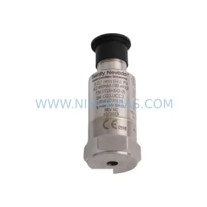
SKU: 177230-00-01-CN 16925-33
Bently Nevada 177230-00-01-CN 16925-33 Service-Ready Spare Part for Industrial Maintenance
Catalog Continuation
Alternative parts within TSI & Rotating Machinery Monitoring.
Stay inside the same system family when you need substitutes, adjacent modules, or a broader shortlist for procurement review.
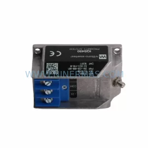
SKU: 204-900-000-011
Vibro-meter 204-900-000-011 Safety-Reliable Vibration Monitor
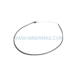
SKU: 330904-00-09-10-02-05/CN
Bently Nevada 330904-00-09-10-02-05/CN Safety-Reliable Vibration Monitor
SKU: 21000-28-05-15-024-03-02
Bently Nevada 21000-28-05-15-024-03-02 Retrofit Proximity Probe