Original Industrial Spare Part
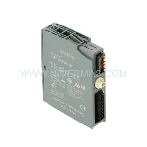
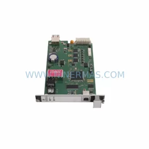
Bently Nevada 21000-16-10-00-046-04-02 Retrofit-Compatible Monitor
Verify the part, confirm the platform family, and move straight into quotation with the right commercial details.
RFQ Ready
- SKU21000-16-10-00-046-04-02
- CategoryTSI & Rotating Machinery Monitoring
- BrandBently Nevada
- SupportAvailability, lead time, condition, and shipping coordination
How Buyers Usually Use This Page
- Confirm the exact part number and platform family before sending the quote request.
- Use direct email when quantity, condition, and destination are already defined internally.
- Switch to the broader brand or category archive when you need alternates nearby.
Series Navigation
Move through the most common platform families behind this part.
Product RFQ
Send this part directly for quotation.
Include quantity, required condition, destination country, and target delivery timing. Current reference: Bently Nevada 21000-16-10-00-046-04-02 Retrofit-Compatible Monitor with SKU 21000-16-10-00-046-04-02.
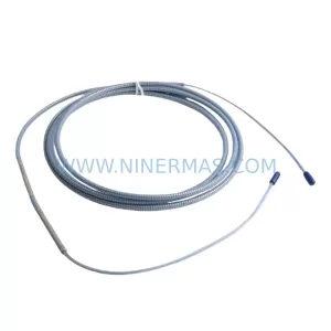
Bently Nevada 21000-16-10-00-046-04-02 Retrofit-Compatible Monitor for Legacy 3300 XL Systems
The Bently Nevada 21000-16-10-00-046-04-02 is a vibration monitor module engineered for the 3300 XL Series machinery protection platform. As original equipment reaches end-of-life and spare parts become increasingly scarce, this unit serves as a proven retrofit-compatible replacement for aging control architectures in rotating machinery protection, turbine monitoring, and critical plant automation environments. NINERMAS maintains verified stock of this module to support emergency replacements, planned outages, and long-cycle maintenance programs across petrochemical, power generation, and heavy industrial facilities.
When integrating the 21000-16-10-00-046-04-02 into an existing 3300 XL rack, engineers must confirm several key parameters before committing to installation. Power supply capacity within the existing rack — typically provided by a 3300/20 Power Supply module — must be verified against the total module load to avoid brownout conditions during startup. Terminal wiring assignments on the I/O termination block must be cross-referenced with the original loop drawings, as transducer signal polarity and shield grounding practices directly affect vibration measurement accuracy. Backplane slot addressing should be confirmed against the rack configuration file to ensure the replacement module is recognized at the correct logical address by the 3500 Rack Configuration Software or equivalent legacy configuration utility.
Program compatibility is another critical checkpoint. If the host system interfaces with a DCS or safety PLC — such as a Rockwell Automation ControlLogix or Honeywell Experion PKS controller — the tag mapping and alarm setpoint database must be validated after module swap. HMI screens built on platforms such as Wonderware InTouch or GE iFIX that display vibration trend data should be tested for correct engineering unit scaling following the replacement. Communication links using Modbus RTU, Modbus TCP, or 4–20 mA analog outputs to upstream systems must be loop-checked to confirm signal integrity before returning the machine to service.
Physical installation space within the existing control cabinet or rack enclosure should be measured prior to ordering. The 21000-16-10-00-046-04-02 occupies a standard 3300 XL single-slot position, but cable routing clearance, cooling airflow, and adjacent module spacing must be assessed — particularly in retrofitted cabinets where third-party I/O modules, signal isolators, or communication gateways have been added over time. Where signal isolation is required between the transducer loop and the control system ground reference, a DIN-rail mounted signal isolator or loop-powered barrier may be inserted without affecting module performance.
Upgrade Compatibility Table
| Parameter | Detail |
|---|---|
| SKU / Part Number | 21000-16-10-00-046-04-02 |
| Brand / Series | Bently Nevada / 3300 XL Series |
| Module Type | Vibration Monitor Module |
| Rack Compatibility | 3300 XL Single-Slot Rack Position |
| Backplane Interface | 3300 XL Standard Backplane |
| Power Supply Requirement | Compatible with 3300/20 Power Supply Module |
| Communication Output | Modbus RTU / Modbus TCP / 4–20 mA Analog |
| Termination | I/O Termination Block (field wiring per loop drawing) |
| Configuration Tool | 3500 Rack Configuration Software / Legacy Utility |
| Replacement Path | Direct drop-in for legacy 21000-series positions |
| Installation Space | Standard single-slot; verify cabinet clearance |
| Commissioning | Loop check, alarm setpoint validation, HMI scaling test |
| Warranty | 12-Month Warranty from NINERMAS |
| Stock Status | In Stock — Ready to Ship |
Retrofit Planning for Existing Automation Systems
A successful retrofit of the 21000-16-10-00-046-04-02 begins with a thorough audit of the existing 3300 XL rack assembly. Technicians should document the current slot population, noting the position of adjacent modules such as the 3300/16 Proximitor Monitor, 3300/46 Dual Voting Logic module, and any 3300/55 Keyphasor module installed in the same rack. These neighboring modules share the backplane data bus, and their configuration files must remain intact during the swap to avoid disrupting the overall machinery protection logic.
Where the control system includes a 3500 Series rack operating in parallel — a common arrangement in phased modernization projects — the 21000-series module may serve as an interim bridge while the facility plans a full migration to the 3500/42M Proximitor/Seismic Monitor or 3500/40M Proximitor Monitor platform. During this transition period, maintaining the existing 3300 XL rack in service while staging the 3500 rack in shadow mode allows operators to validate alarm thresholds and trip setpoints without interrupting production.
For facilities upgrading communication infrastructure, the addition of a 3500/92 Communication Gateway module to the 3500 rack enables Ethernet-based data transfer to plant historians and condition monitoring platforms, replacing legacy serial Modbus links. Signal conditioning between the old and new rack environments may require a DIN-rail signal isolator or a dedicated I/O marshalling panel to manage ground loop differences and cable shield continuity across the two systems.
Power distribution within the control cabinet should be re-evaluated during any retrofit. The existing 3300/20 Power Supply module may be operating near its rated capacity if additional I/O cards or communication modules have been added since original commissioning. A load calculation covering all installed modules — including any 3300 XL I/O expansion cards and external 24 VDC field device loops — should be completed before the replacement module is energized. If the power budget is marginal, a supplementary DIN-rail power supply unit can be added to the cabinet to support the additional load without replacing the existing rack power supply.
Programming cable access is also a practical consideration. If the site uses a dedicated programming laptop with the 3500 Rack Configuration Software, the RS-232 or USB-to-serial programming cable must be available on-site during commissioning. Verifying that the laptop’s software version is compatible with the firmware revision of the replacement module prevents configuration upload failures during the critical post-installation checkout phase.
Downtime Control During System Migration
Minimizing unplanned downtime during a 3300 XL module replacement requires a structured pre-outage preparation process. Before the maintenance window opens, the existing module configuration should be exported and saved to a secure backup location using the 3500 Rack Configuration Software or the applicable legacy configuration tool. This backup preserves all alarm setpoints, trip multipliers, transducer sensitivity values, and channel enable/disable states, allowing the replacement module to be pre-configured on the bench before the outage begins.
During the outage, the sequence of operations should follow a defined isolation procedure: de-energize the rack power supply, extract the failed or end-of-life module, insert the 21000-16-10-00-046-04-02 replacement, re-energize, and upload the pre-validated configuration file. This approach compresses the active installation window to under 30 minutes in most cases, provided that the termination block wiring is undisturbed and the replacement module has been pre-tested at the NINERMAS facility prior to shipment.
Field commissioning should include a full loop check on each transducer channel, verification of OK relay output states, confirmation of alarm and danger relay operation using a calibrated signal simulator, and a final review of the communication link status to the upstream DCS or safety system. HMI screens displaying vibration amplitude, gap voltage, and machine speed should be observed through at least one complete machine start-up cycle to confirm that all displayed values are within expected engineering unit ranges before the maintenance team signs off on the work order.
Where the machine cannot be taken offline for an extended period, a hot-swap strategy using a pre-staged spare rack — populated with a pre-configured 21000-16-10-00-046-04-02 and associated modules — can reduce the active changeover time to the duration of a single cable transfer and rack substitution. NINERMAS can support this approach by supplying pre-tested, pre-configured modules with documentation packages that include as-found and as-left configuration reports.
Retrofit Support FAQ
Q1: Is the 21000-16-10-00-046-04-02 a direct replacement for the original module in my 3300 XL rack?
Yes. The 21000-16-10-00-046-04-02 is designed to occupy the same single-slot backplane position as the original 21000-series module. Termination block wiring, slot addressing, and configuration file structure are compatible with the existing 3300 XL rack architecture. Minor firmware differences between production batches may require a configuration file review before upload, which NINERMAS technical support can assist with remotely.
Q2: What commissioning steps are required after installation?
After physical installation, the replacement module must be configured using the 3500 Rack Configuration Software or the applicable legacy utility. Required steps include uploading the saved configuration file, performing a channel-by-channel loop check with a calibrated signal source, verifying OK and alarm relay output states, and confirming communication link status to the upstream control system. NINERMAS provides a commissioning checklist with every shipment to guide on-site technicians through the process.
Q3: How do I verify wiring compatibility before installation?
Compare the existing loop drawings against the 21000-16-10-00-046-04-02 termination block pinout diagram. Pay particular attention to transducer signal polarity, shield grounding terminal assignments, and OK relay wiring. If the original loop drawings are unavailable, NINERMAS can provide the standard termination reference document for this module upon request.
Q4: What warranty and stock availability does NINERMAS offer?
All 21000-16-10-00-046-04-02 units supplied by NINERMAS carry a 12-month warranty covering manufacturing defects and functional performance. Units are pre-tested prior to shipment and include a test report. NINERMAS maintains standing inventory of this module to support both emergency same-week dispatch and planned procurement programs. Contact sale@ninermas.com or +0086 187 5021 5667 for current stock confirmation and lead time.
| Product Series | 21000 series |
|---|---|
| Country of Origin | US |
Catalog Continuation
More Bently Nevada modules in the catalog.
Use the brand lane to compare nearby part numbers, platform-adjacent modules, and other inquiry-ready listings before sending your final RFQ.
SKU: 330191-00-33-90-05
Bently Nevada 330191-00-33-90-05 Service-Ready Spare Part
SKU: 330104-00-05-50-02-00
Bently Nevada 330104-00-05-50-02-00 Proximity Sensor Module
SKU: 330703-000-040-10-02-CN
Bently Nevada 330703-000-040-10-02-CN Retrofit Proximity Module
SKU: 330104-06-14-10-02-00
Bently Nevada 330104-06-14-10-02-00 Safety-Reliable Proximity Transducer
Catalog Continuation
Alternative parts within TSI & Rotating Machinery Monitoring.
Stay inside the same system family when you need substitutes, adjacent modules, or a broader shortlist for procurement review.

SKU: APP1407030-00100
Bently Nevada APP1407030-00100 Safety-Reliable Proximity Probe
SKU: 21000-16-10-35-098-03-02
Bently Nevada 21000-16-10-35-098-03-02 Retrofit-Compatible Proximity Transducer
SKU: 21000-16-10-15-029-03-02
Bently Nevada 21000-16-10-15-029-03-02 Retrofit Proximity Probe Housing