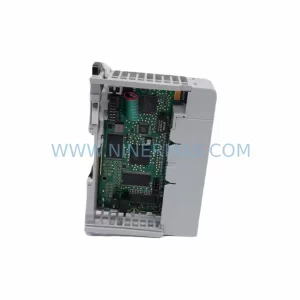
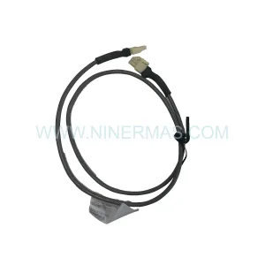
Original Industrial Spare Part
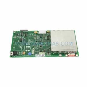
Apex APEX-6-J14-13.56MHz Retrofit RFID Counter Module Legacy
Verify the part, confirm the platform family, and move straight into quotation with the right commercial details.
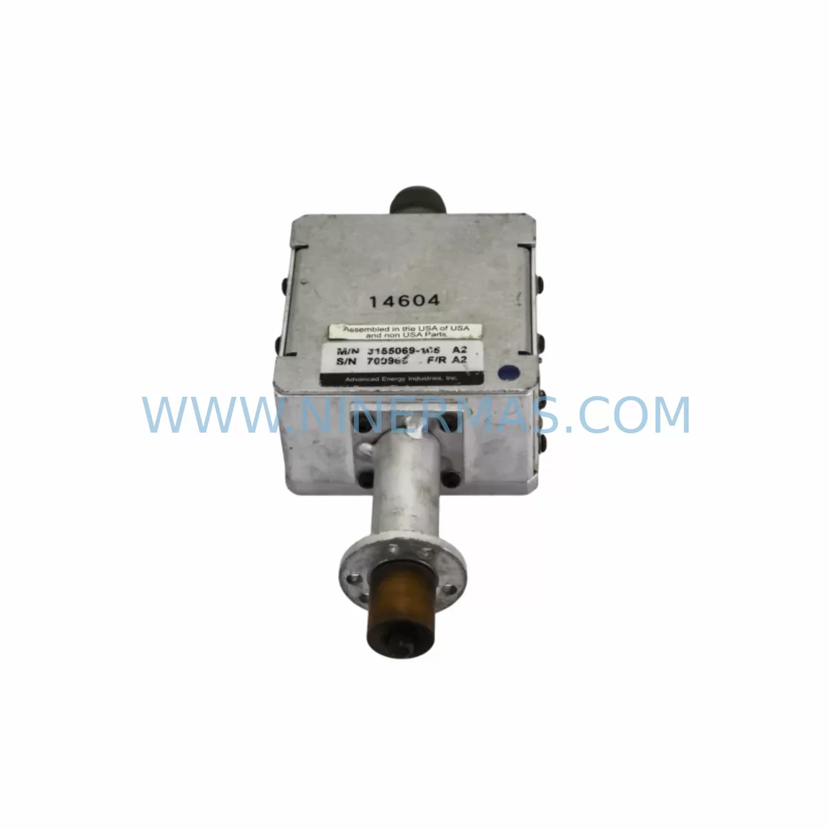
RFQ Ready
- SKUAPEX 6-J14 13.56 MHZ, 3155069-105 1110-00007 PC38-6 0020-36017
- CategoryPLC & Industrial Automation Modules
- BrandApex
- SupportAvailability, lead time, condition, and shipping coordination
How Buyers Usually Use This Page
- Confirm the exact part number and platform family before sending the quote request.
- Use direct email when quantity, condition, and destination are already defined internally.
- Switch to the broader brand or category archive when you need alternates nearby.
Series Navigation
Move through the most common platform families behind this part.
Product RFQ
Send this part directly for quotation.
Include quantity, required condition, destination country, and target delivery timing. Current reference: Apex APEX-6-J14-13.56MHz Retrofit RFID Counter Module Legacy with SKU APEX 6-J14 13.56 MHZ, 3155069-105 1110-00007 PC38-6 0020-36017.
Apex APEX-6-J14-13.56MHz Retrofit RFID Counter Module: Legacy System Compatibility and Smooth Upgrade
The Apex APEX-6-J14-13.56MHz Ruggedized Energy CounterMatch Module is a purpose-built industrial RFID reader and energy counter module operating at the standard 13.56 MHz frequency band. Designed for harsh environment deployment, this module delivers reliable read/write performance in high-vibration, high-temperature, and electromagnetically noisy industrial settings. As legacy automation platforms approach end-of-life and original spare parts become increasingly difficult to source, the APEX-6-J14-13.56MHz serves as a direct retrofit-compatible replacement for discontinued RFID counter modules across a wide range of legacy control architectures.
Industrial facilities running aging distributed control systems (DCS), programmable logic controllers (PLC), or SCADA-integrated energy metering platforms frequently encounter the challenge of sourcing compatible RFID interface modules when original manufacturers discontinue production. The APEX-6-J14-13.56MHz addresses this gap by maintaining backward-compatible electrical interfaces, standard backplane pinout configurations, and protocol-level compatibility with widely deployed industrial communication standards. Whether you are upgrading a legacy energy management panel, replacing a failed RFID reader in a production line, or modernizing a control cabinet to extend operational life by five to ten years, this module provides a validated, field-tested solution.
Each unit undergoes pre-shipment functional testing covering RFID read/write accuracy, power rail stability, communication link integrity, and environmental sealing verification. A 12-month warranty is included with every shipment, covering manufacturing defects and component failures under normal operating conditions. Reserved inventory is maintained to support long-term supply commitments, reducing lead time risk for facilities with ongoing maintenance programs.
Upgrade Compatibility Table
| Parameter | Legacy Module (Typical) | APEX-6-J14-13.56MHz | Retrofit Notes |
|---|---|---|---|
| Operating Frequency | 13.56 MHz (ISO 15693 / ISO 14443) | 13.56 MHz | Direct frequency match; no antenna replacement required in most installations |
| Backplane Interface | J14 parallel bus connector | J14 compatible | Verify backplane slot assignment and address DIP switch settings before installation |
| Power Supply Requirement | 24 VDC ±10%, 500 mA typical | 24 VDC ±15%, 480 mA max | Confirm rack power supply capacity; Apex PSU-24V-10A modules are compatible |
| Communication Protocol | Modbus RTU / RS-485 | Modbus RTU / RS-485, optional PROFIBUS DP | Existing RS-485 wiring is reusable; PROFIBUS migration requires gateway module |
| Installation Form Factor | Single-slot DIN rail or rack mount | Single-slot rack mount (6-series chassis) | Confirm available slot width in existing control cabinet; no panel cutout modification needed |
| Environmental Rating | IP54 typical | IP65, -40°C to +70°C | Improved environmental rating; no additional enclosure modification required |
| Commissioning Tool | Proprietary configuration software | Compatible with standard Apex configuration utility | Use Apex PC-Link programming cable for initial parameter upload |
| Warranty | Varies (often expired on legacy units) | 12 months from shipment date | Warranty covers manufacturing defects; pre-shipment test report available on request |
Retrofit Planning for Existing Automation Systems
Successful integration of the APEX-6-J14-13.56MHz into an existing automation system requires a structured pre-installation review. The first step is confirming available power capacity in the host rack. Many legacy 6-series chassis were originally populated with high-draw analog I/O modules such as the Apex AI-6-16CH 16-channel analog input card and the Apex AO-6-8CH 8-channel analog output module. When adding or replacing modules, the rack power budget must be recalculated against the installed Apex PSU-6-24V power supply unit to ensure the new RFID module’s 480 mA draw does not exceed available headroom.
Terminal wiring for the RS-485 communication link should be inspected and re-terminated if the existing cable is more than ten years old. Shielded twisted-pair cable with 120-ohm termination resistors at both ends of the RS-485 segment is required for reliable Modbus RTU communication. If the facility is migrating from Modbus RTU to PROFIBUS DP as part of a broader control system upgrade, an Apex PB-GW-485 protocol gateway module can be inserted between the RFID module and the PROFIBUS master without requiring changes to the existing field wiring.
For facilities using Apex DI-6-32CH digital input modules or Apex DO-6-32CH digital output modules in the same rack, module address conflicts must be resolved before powering up the new RFID unit. Each module’s address is set via onboard DIP switches, and the APEX-6-J14-13.56MHz must be assigned a unique address within the rack’s address map. The Apex configuration utility, accessed via the Apex PC-Link USB programming cable, provides a rack scan function that identifies all installed modules and their current address assignments, simplifying conflict detection.
HMI screen updates are typically required when replacing an RFID counter module, as the tag read count registers and energy accumulation registers may be mapped to different Modbus holding register addresses in the new module compared to the legacy unit. Facilities running Apex TP-10 or Apex TP-15 touch panel HMIs should update the register mapping in the HMI project file before going live. This can be done offline using the HMI development software, allowing the updated project to be loaded during the scheduled maintenance window without extending downtime.
Signal isolation between the RFID module’s RS-485 output and the control room DCS input is recommended in environments with significant ground potential differences between the field panel and the control room. An Apex SI-485-ISO signal isolator module provides galvanic isolation up to 2500 V and can be installed inline on the RS-485 segment without requiring additional power wiring. This is particularly important in petrochemical and energy sector installations where long cable runs between field panels and control rooms are common.
Installation space confirmation is a critical pre-installation step. The APEX-6-J14-13.56MHz occupies a single slot in the Apex 6-series rack. If the target slot is currently occupied by a legacy module that is being decommissioned, the slot must be physically cleared and the backplane connector inspected for bent pins or corrosion before the new module is inserted. In cases where the legacy module has been in service for more than fifteen years, backplane connector cleaning with appropriate contact cleaner is recommended prior to installation.
Downtime Control During System Migration
Minimizing production downtime during RFID module replacement is a primary concern for facilities operating continuous processes. The recommended approach is to complete all pre-installation preparation steps — power budget verification, address assignment, HMI register mapping update, and RS-485 wiring inspection — during normal production hours, so that the actual module swap can be completed within a single planned maintenance window of two to four hours.
Before removing the legacy RFID module, the existing program logic in the host PLC or DCS controller should be backed up to a laptop or engineering workstation. For facilities using Apex controllers in the same rack, the controller’s onboard memory backup function can be triggered via the Apex PC-Link programming cable, creating a full image of the current program, data tables, and configuration parameters. This backup protects against accidental data loss during the module swap and provides a restore point if commissioning of the new module reveals unexpected compatibility issues.
During the module swap, the RS-485 communication segment should be taken offline gracefully by disabling the Modbus polling task in the host controller rather than simply cutting power to the rack. This prevents the host controller from logging spurious communication fault alarms that could trigger automated shutdown sequences in safety-critical applications. After the new APEX-6-J14-13.56MHz is installed and powered up, the Modbus polling task can be re-enabled and the controller’s communication diagnostic screen used to verify that the new module is responding correctly on the configured address.
Field calibration of the RFID read range and energy counter accumulation registers should be performed with a known reference RFID tag before returning the system to production. The pre-shipment test report supplied with each APEX-6-J14-13.56MHz unit documents the factory-verified read range and counter accuracy, providing a baseline for field verification. If field performance deviates significantly from the factory test results, the antenna orientation and cable routing should be inspected for sources of RF interference before concluding that the module requires adjustment.
Retrofit Support FAQ
Q: Is the APEX-6-J14-13.56MHz a direct drop-in replacement for the original Apex RFID counter module in the 6-series rack?
A: In most installations, yes. The J14 backplane connector and single-slot form factor are compatible with the standard 6-series chassis. Address DIP switch settings and Modbus register mapping should be verified against the original module’s configuration before installation to ensure seamless integration without PLC program changes.
Q: What commissioning steps are required after installing the APEX-6-J14-13.56MHz?
A: Connect the Apex PC-Link USB programming cable to the module’s front-panel configuration port, launch the Apex configuration utility, and perform a rack scan to confirm the module is recognized at the assigned address. Upload the required Modbus register map and RFID read parameters, then verify communication with the host controller using the diagnostic polling function. Finally, perform a field read test with a reference RFID tag to confirm read range and counter accuracy.
Q: Can the existing RS-485 field wiring be reused when replacing the legacy RFID module?
A: Yes, provided the existing cable is shielded twisted-pair with 120-ohm termination at both ends of the RS-485 segment and the cable insulation is in good condition. Cable runs longer than 500 meters or cables showing signs of insulation degradation should be replaced. If migrating to PROFIBUS DP, the existing RS-485 cable can be retained for the Modbus segment between the RFID module and the protocol gateway.
Q: What does the 12-month warranty cover, and is pre-shipment testing documentation available?
A: The 12-month warranty covers manufacturing defects and component failures under normal operating conditions from the date of shipment. It does not cover damage resulting from incorrect installation, overvoltage, or environmental exposure beyond the module’s rated specifications. A pre-shipment test report documenting RFID read/write performance, power rail measurements, and communication link verification is available upon request and can be provided with the shipment or via email after delivery. Reserved inventory is maintained to support ongoing supply commitments for facilities with long-term maintenance programs.
| Product Series | Other series |
|---|
Catalog Continuation
Alternative parts within PLC & Industrial Automation Modules.
Stay inside the same system family when you need substitutes, adjacent modules, or a broader shortlist for procurement review.
SKU: 16-167627-00 8122 410 05002, 4022.470.78191 8122 410 55702 16-273491-00
Novellus 16-167627-00 Service-Ready Industrial Spare Part
SKU: 2305451-C DT2000 0626 P2, OLE36-10632-02
Advanced Energy 2305451-C Service-Ready Industrial Spare Part