Original Industrial Spare Part
Allen-Bradley 81000-199-52-R Service-Ready Spare Part
Verify the part, confirm the platform family, and move straight into quotation with the right commercial details.
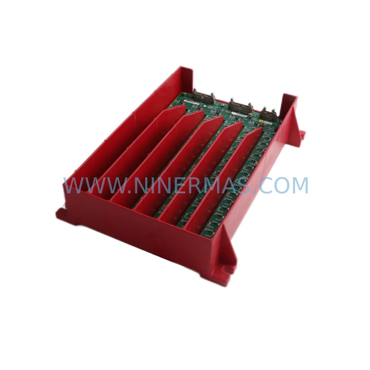
RFQ Ready
- SKU81000-199-52-R
- CategoryPLC & Industrial Automation Modules
- BrandAllen-Bradley
- SupportAvailability, lead time, condition, and shipping coordination
How Buyers Usually Use This Page
- Confirm the exact part number and platform family before sending the quote request.
- Use direct email when quantity, condition, and destination are already defined internally.
- Switch to the broader brand or category archive when you need alternates nearby.
Series Navigation
Move through the most common platform families behind this part.
Product RFQ
Send this part directly for quotation.
Include quantity, required condition, destination country, and target delivery timing. Current reference: Allen-Bradley 81000-199-52-R Service-Ready Spare Part with SKU 81000-199-52-R.
Allen-Bradley 81000-199-52-R Service-Ready Spare Part for Industrial Maintenance
The Allen-Bradley 81000-199-52-R is a critical service-ready spare part designed for the SLC 500 series programmable logic controller platform — one of the most widely deployed control architectures in discrete manufacturing, material handling, automotive assembly, and process automation environments. When a control system fault occurs on the SLC 500 rack, every minute of unplanned downtime translates directly into production loss. Stocking the 81000-199-52-R as a verified replacement unit is a proven strategy for maintenance engineers who need to restore operations quickly, confidently, and without compatibility risk.
At NINERMAS, every unit of the 81000-199-52-R is sourced, inspected, and dispatched with a 12-month warranty. Our supply chain is built for industrial buyers who cannot afford counterfeit components, long lead times, or untested stock. Each unit undergoes pre-shipment functional verification before leaving our facility, giving your maintenance and procurement teams the assurance needed to proceed with a planned or emergency replacement.
Spare Maintenance Table
| Parameter | Details |
|---|---|
| Part Number / SKU | 81000-199-52-R |
| Brand | Allen-Bradley |
| Series | SLC 500 |
| Product Type | PLC Spare Part / Replacement Module |
| Compatibility | Allen-Bradley SLC 500 series control systems |
| Origin | United States (USA) |
| Application Environment | Industrial automation, discrete manufacturing, process control |
| Installation | Rack-mount, SLC 500 backplane compatible |
| Maintenance Recommendation | Replace during scheduled annual overhaul or upon fault indication; verify backplane seating and I/O wiring continuity post-installation |
| Warranty | 12 Months — tested and verified before shipment |
| Condition | New / Service-Ready Original |
| Lead Time | In-stock; ready for immediate dispatch |
Maintenance Planning for Continuous Operation
Replacing the 81000-199-52-R in a live SLC 500 system is rarely an isolated task. Experienced maintenance engineers understand that a module fault in one part of the control cabinet often signals stress or degradation in adjacent components. When performing a replacement of this spare part, a thorough site inspection should include the following associated components to prevent repeat failures and ensure full system restoration.
Begin with the SLC 500 power supply module (such as the 1746-P4 or 1746-P7). A failing or under-rated power supply is a common root cause of module faults and should be load-tested before the replacement unit is commissioned. Next, inspect the SLC 500 backplane and chassis (1746-A4, 1746-A7, or 1746-A13 depending on slot count) for signs of corrosion, bent connector pins, or thermal damage — backplane integrity is essential for reliable module communication.
Review all digital and analog I/O modules in the rack, including 1746-IB16 input modules and 1746-OB16 output modules, for blown fuses, wiring faults, or field device failures that may have contributed to the original fault condition. Check relay output modules and associated terminal blocks for contact wear, especially in high-cycle applications. Inspect communication modules such as the 1747-SDN DeviceNet scanner or 1747-KE DH-485 interface for firmware version compatibility and network integrity after the replacement is installed.
For systems with signal isolation requirements, verify that any installed signal isolators or barriers between field instruments and I/O cards are functioning within specification. Examine 24VDC field power distribution — including fuse blocks, terminal strips, and DIN rail-mounted power supplies — for signs of overload or intermittent supply. If the control cabinet includes an HMI panel (such as a PanelView 550 or PanelView Plus), confirm that communications to the SLC 500 processor are re-established and all screen tags are updating correctly after the module swap.
Finally, review the SLC 500 processor module (1747-L532 or 1747-L543) battery status and program backup. A replacement event is the ideal time to verify that the processor program is backed up to an SD card or PC-based programming terminal using RSLogix 500, and that the processor firmware is current. Proactive inspection of these interconnected components during a planned or emergency replacement of the 81000-199-52-R significantly reduces the risk of secondary failures and repeat downtime events.
Site Replacement Workflow
When the 81000-199-52-R arrives on site, follow a structured replacement workflow to minimize downtime and ensure system compatibility. Begin by placing the SLC 500 processor in Program mode via the key switch before removing any modules — never hot-swap SLC 500 modules without confirming the processor state and understanding the impact on connected field devices.
Document the existing wiring configuration and I/O addressing before removal. Photograph terminal connections and label all field wiring if not already marked. Remove the faulty module by releasing the locking tab and sliding it clear of the backplane. Inspect the backplane connector for damage before inserting the 81000-199-52-R replacement unit. Seat the module firmly until the locking tab engages.
After installation, restore power and place the processor back into Run mode. Monitor the I/O status indicators and verify that all field devices are responding correctly. Use RSLogix 500 or Studio 5000 Logix Designer (if applicable) to confirm that no fault codes are present and that the replacement module is recognized by the processor. Perform a functional test of all outputs controlled by the replaced module before returning the line to production.
This workflow is applicable whether the 81000-199-52-R is being installed as an emergency replacement during an unplanned outage or as part of a scheduled annual maintenance overhaul. Maintaining a documented replacement procedure reduces technician error, shortens mean time to repair (MTTR), and supports audit trail requirements in regulated manufacturing environments.
Spare Parts Support FAQ
Q1: Is the 81000-199-52-R covered by a warranty, and what does it include?
Yes. Every 81000-199-52-R unit supplied by NINERMAS carries a 12-month warranty from the date of shipment. This covers manufacturing defects and functional failures under normal operating conditions. Each unit is tested prior to dispatch to confirm it meets original specification. If a unit fails within the warranty period, NINERMAS will arrange a replacement or repair at no additional cost.
Q2: How do I verify compatibility between the 81000-199-52-R and my existing SLC 500 system?
Compatibility is determined by the SLC 500 chassis type, power supply rating, and the slot position within the rack. Cross-reference the part number against your existing system documentation or the original Allen-Bradley catalog. If you are unsure, contact our technical team with your system configuration details — we can confirm compatibility before you place an order, eliminating procurement risk.
Q3: Can NINERMAS support long-term or repeat supply of the 81000-199-52-R for ongoing maintenance programs?
Yes. NINERMAS specializes in long-term spare parts supply for industrial automation systems, including legacy and discontinued Allen-Bradley product lines. We support blanket purchase orders, scheduled delivery programs, and consignment stock arrangements for maintenance teams managing large installed bases of SLC 500 equipment. Contact our sales team to discuss a supply agreement tailored to your annual maintenance budget.
Q4: What is the recommended inventory strategy for the 81000-199-52-R in a multi-line facility?
For facilities operating multiple SLC 500-based production lines, we recommend maintaining a minimum of one spare unit per critical line, with an additional buffer unit held in the central maintenance store. Given the age of the SLC 500 platform and the increasing difficulty of sourcing original Allen-Bradley spare parts through standard distribution channels, early procurement and strategic stocking are strongly advised. NINERMAS can assist with a spare parts audit and stocking recommendation based on your installed equipment list.
| Product Series | SLC 500 |
|---|---|
| Country of Origin | US |
Catalog Continuation
More Allen-Bradley modules in the catalog.
Use the brand lane to compare nearby part numbers, platform-adjacent modules, and other inquiry-ready listings before sending your final RFQ.
Catalog Continuation
Alternative parts within PLC & Industrial Automation Modules.
Stay inside the same system family when you need substitutes, adjacent modules, or a broader shortlist for procurement review.
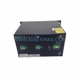
SKU: SCE906A2-002-01 SCE906A200201
Pacific Scientific SCE906A2-002-01 Retrofit Servo Amplifier
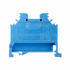
SKU: EPC500 3183062451
Alfa Laval EPC500 3183062451 Service-Ready Spare Part