Allen-Bradley 1797-OB4D Digital Output Module | 4-Ch Source I/O for Hazardous Locations
Description
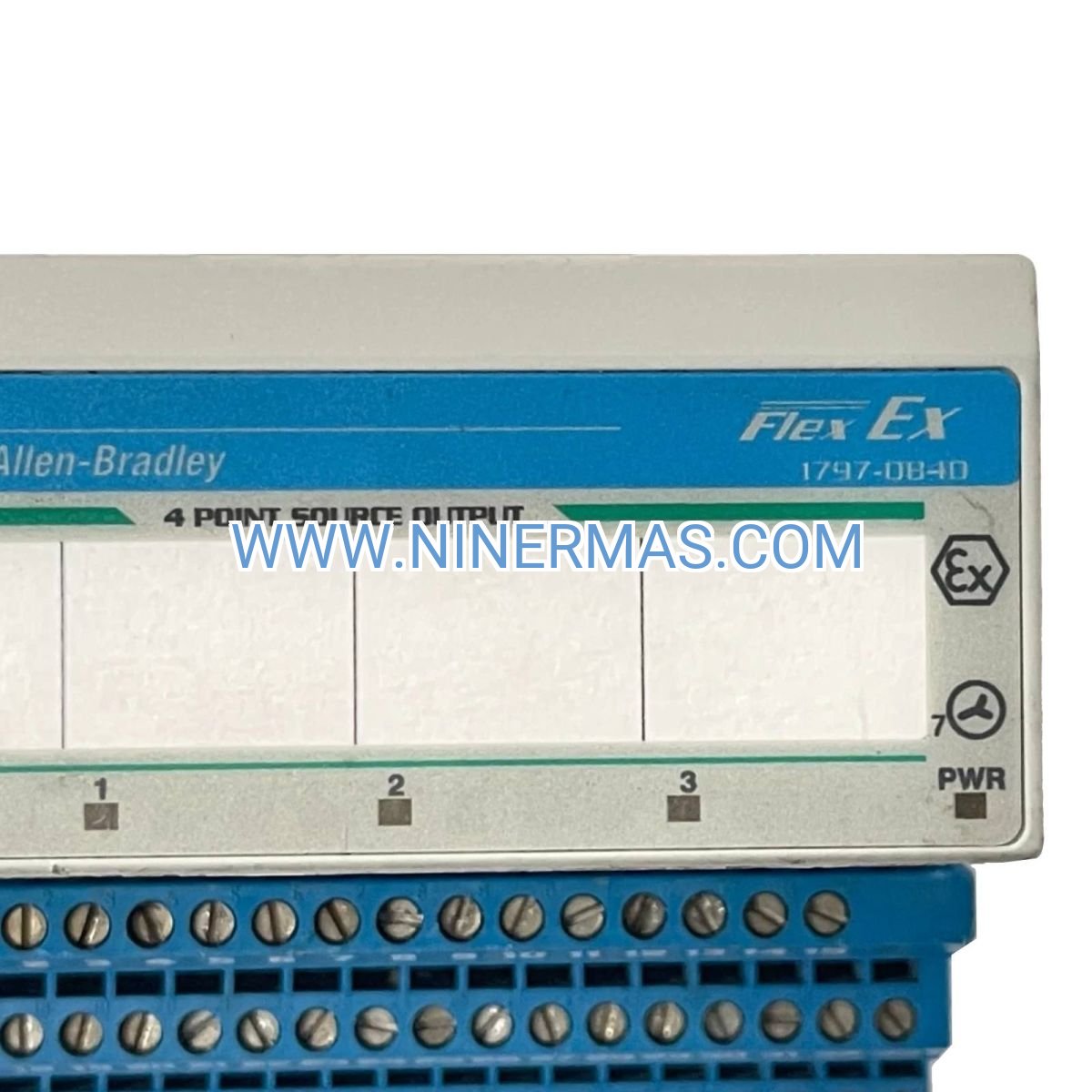
Allen-Bradley 1797-OB4D Flex Ex Digital Output Module (Industrial-Grade 4-Channel Source I/O System)
The Allen-Bradley 1797-OB4D is a professional-grade digital output module engineered for hazardous location control applications, delivering reliable 4-channel source output through advanced Flex Ex I/O architecture. Utilizing non-isolated output technology and intrinsically safe design principles, this module enables precise control of field devices in Zone 2 and Division 2 classified areas while maintaining hot-swappable capability for minimal downtime.
Designed for petrochemical facilities, oil & gas processing plants, pharmaceutical manufacturing environments, paint spray booths, and grain handling operations, this module addresses critical challenges including explosive atmosphere safety compliance, system reliability in harsh conditions, rapid module replacement requirements, and integration with distributed control architectures.
Through certified hazardous location ratings and modular Flex Ex design, the 1797-OB4D delivers intrinsic safety protection, field-proven durability, tool-free hot-swap maintenance, and seamless compatibility with Rockwell Automation control platforms. Ideal for system integrators, control panel builders, plant maintenance teams, and automation engineers requiring compliant solutions. Contact our application engineers for hazardous area classification guidance and system configuration support.
Core Features & Technical Advantages
- Certified Hazardous Location Protection
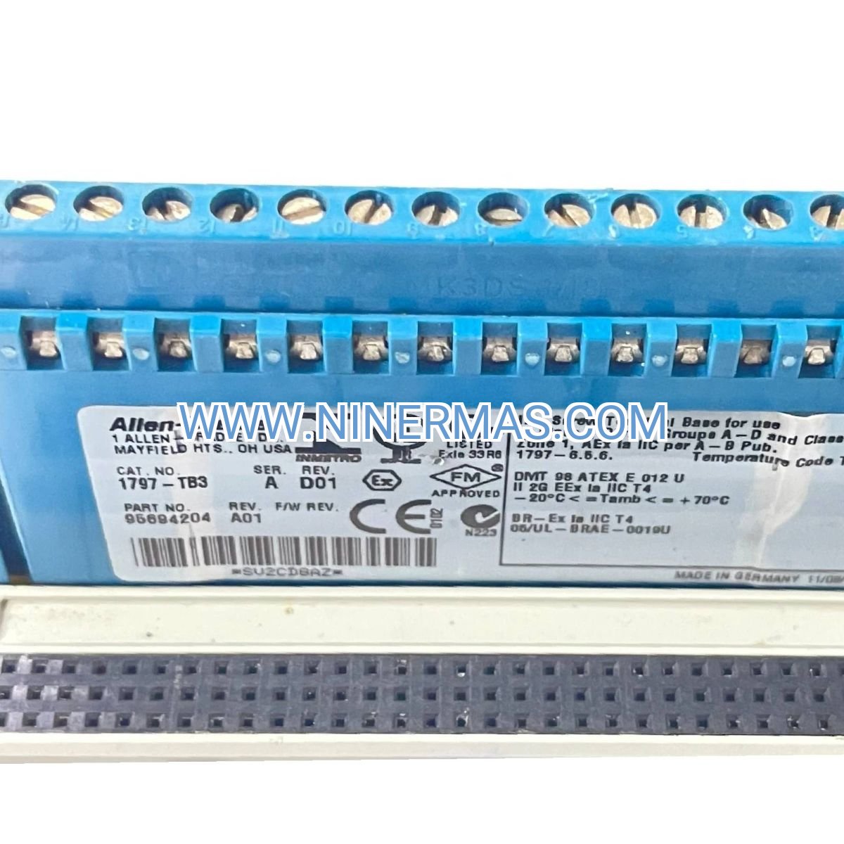
Class I Division 2 Groups A, B, C, D and Zone 2 IIC certified design ensures safe operation in explosive atmospheres, meeting global safety standards including ATEX, IECEx, and NEC requirements for critical industrial environments. - Hot-Swappable Modular Architecture
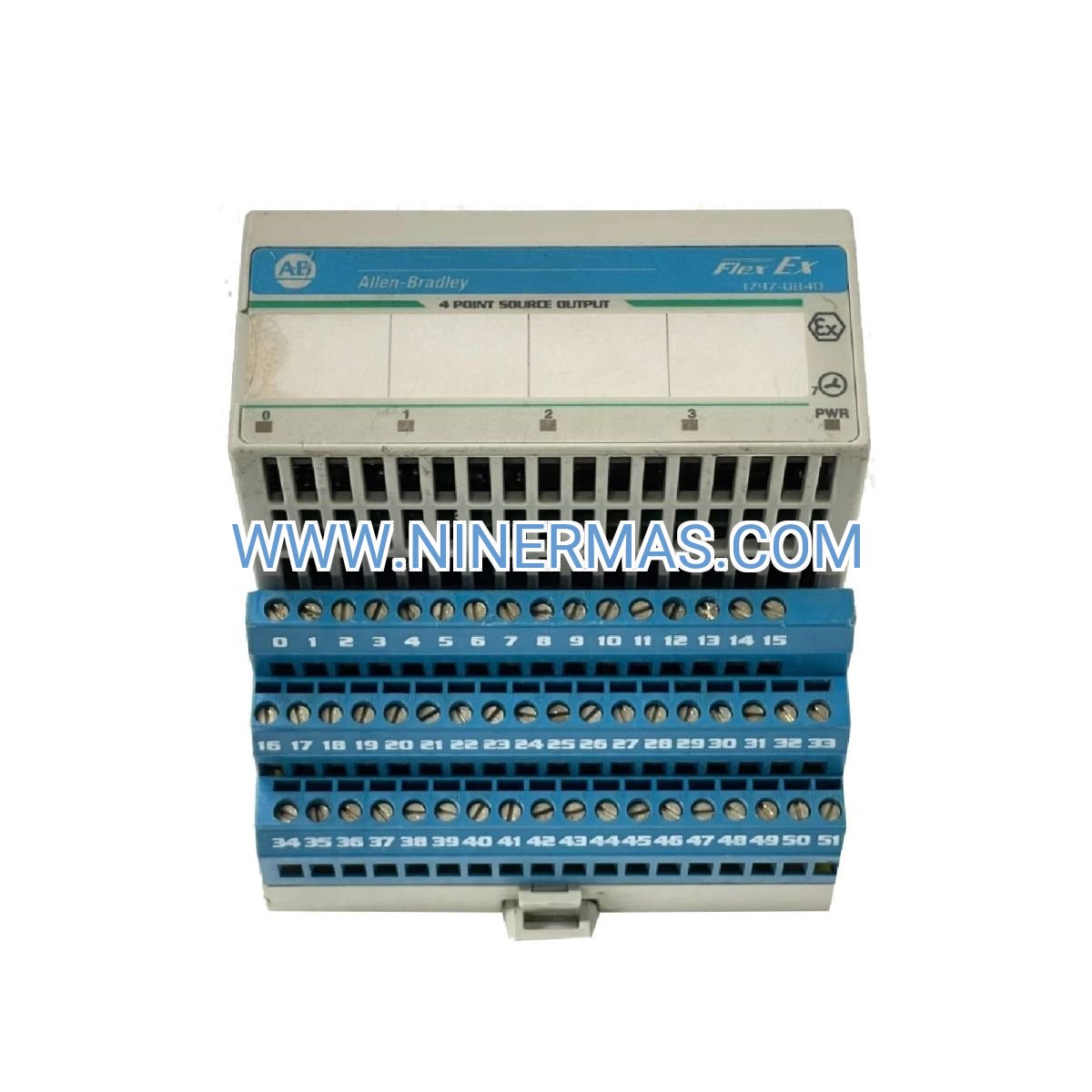
Field-replaceable design allows module exchange under power without system shutdown, reducing maintenance windows by up to 80% and enabling rapid fault recovery in continuous process applications. - 4-Channel Source Output Configuration
Independent sourcing outputs (24V DC nominal) provide direct control of solenoid valves, indicator lights, and actuators with per-channel diagnostic capability and short-circuit protection for enhanced system reliability. - Flex Ex Distributed I/O Integration
Native compatibility with 1797 Flex Ex adapters and ControlLogix/CompactLogix platforms enables scalable I/O expansion, supporting up to 8 modules per adapter with DeviceNet or EtherNet/IP communication protocols. - Comprehensive Diagnostic & Protection
Built-in channel-level fault detection, overload protection, reverse polarity safeguards, and LED status indicators minimize troubleshooting time while protecting connected field devices from electrical damage. - Compact DIN-Rail Mounting Design
Space-efficient 35mm DIN-rail compatible housing (approximately 35 x 118 x 87 mm) optimizes panel real estate, with IP20 enclosure rating suitable for controlled industrial cabinet environments.
Typical Application Scenarios
This module excels in applications demanding certified safety, operational continuity, and distributed control architecture:
- Petrochemical & Refinery Process Control
Controls emergency shutdown valves, pump interlocks, and alarm annunciators in classified areas, ensuring compliance with API and NFPA standards while maintaining process safety integrity. - Oil & Gas Wellhead & Pipeline Automation
Manages remote actuator control, flow diversion valves, and safety instrumented systems in Zone 2 offshore platforms and onshore gathering stations, withstanding temperature extremes and vibration. - Pharmaceutical Clean Room Manufacturing
Operates material transfer valves, isolator controls, and environmental monitoring systems in Division 2 solvent handling areas, supporting FDA 21 CFR Part 11 compliant automation architectures. - Paint & Coating Application Systems
Drives spray booth dampers, solvent vapor controls, and conveyor interlocks in Class I Division 2 finishing operations, reducing fire hazard risks while maintaining production throughput. - Grain Handling & Food Processing Facilities
Controls dust collection systems, bin level indicators, and conveyor sequencing in combustible dust environments, meeting NFPA 61 and OSHA grain handling safety requirements.
Technical Specifications & Selection Guide
To facilitate engineering design and procurement, we provide standardized electrical, environmental, and mechanical parameters with application-specific configuration options:
| Parameter | Specification |
|---|---|
| Output Channels | 4 independent source outputs |
| Output Type | Non-isolated sourcing (positive switching) |
| Voltage Range | 10-30V DC nominal (24V DC typical) |
| Current per Channel | 2A maximum continuous, 4A peak (100ms) |
| Hazardous Location Rating | Class I Div 2 Groups A-D, Zone 2 IIC |
| Operating Temperature | -20°C to +60°C (-4°F to +140°F) |
| Communication Protocol | Via Flex Ex adapter (DeviceNet/EtherNet/IP) |
| Power Consumption | Approx. 1.5W from backplane + output load |
| Mounting | 35mm DIN rail (EN 50022) |
| Enclosure Rating | IP20 (for use in controlled cabinets) |
| Diagnostic Indicators | Module status LED + per-channel fault LEDs |
| Certifications | UL/cUL, ATEX, IECEx, CE, RCM |
Selection Considerations: When specifying this module, evaluate total output current requirements (sum of all channels ≤6A), field device voltage compatibility, required communication network (DeviceNet vs. EtherNet/IP adapter selection), hazardous area classification documentation, and panel ambient temperature conditions. For systems requiring input modules, consider pairing with 1797-IB8 or 1797-IE8 companion modules. Our application engineers can review P&ID drawings and provide bill-of-materials recommendations.
System Integration & Expansion Capabilities
- Multi-Protocol Network Support: Compatible with 1797-FLX series adapters supporting DeviceNet (1797-DN) and EtherNet/IP (1797-AENTR) for flexible network architecture integration
- Mixed I/O Configuration: Combine with analog input (1797-IE8), digital input (1797-IB16), and relay output (1797-OE4) modules on single adapter for comprehensive I/O density
- Redundant System Design: Supports ControlLogix redundancy configurations when paired with redundant Flex Ex adapters for high-availability applications
- Remote Monitoring Integration: Diagnostic data accessible via RSLogix 5000/Studio 5000 software for predictive maintenance and SCADA system integration
- Third-Party Device Compatibility: Standard 24V DC output interfaces with solenoid valves (ASCO, Bürkert), pilot lights (Banner, Patlite), and actuators from major industrial suppliers
Delivery, Service & Quality Assurance
Standard catalog items typically ship within 3-5 business days from regional distribution centers; custom-configured systems or bulk orders require 10-15 business days lead time. All modules include a comprehensive 12-month manufacturer warranty covering defects in materials and workmanship, with extended service agreements available for critical applications.
Technical support includes remote configuration assistance via phone/email, on-site commissioning services (subject to location and scope), and access to detailed documentation package containing wiring diagrams (publication 1797-UM005), installation instructions, and RSLogix programming examples. Our engineering team provides application notes for hazardous area installations and can coordinate third-party certification reviews when required.
Each module ships with complete technical documentation set including electrical schematics, terminal block wiring diagrams, hazardous location certification certificates, and quick-start installation guide to streamline panel integration and field startup procedures.
Frequently Asked Questions (FAQ)
Q: How does the 1797-OB4D digital output module integrate with existing Allen-Bradley PLC systems?
A: The module connects via a 1797 Flex Ex adapter (DeviceNet or EtherNet/IP) which communicates with ControlLogix, CompactLogix, or SLC 500 controllers. Configuration requires RSLogix/Studio 5000 software to map I/O addresses and enable diagnostics. Verify adapter compatibility and available I/O slot capacity before ordering.
Q: What is the maximum number of output modules supported on a single Flex Ex adapter?
A: Each 1797 adapter supports up to 8 I/O modules (mix of input/output types), with total backplane current limited to 3A at 24V DC. The 1797-OB4D consumes approximately 1.5W plus connected load, allowing 5-7 modules depending on configuration. Consult publication 1797-UM005 for detailed power budgeting.
Q: Can this module be used in Class I Division 1 or Zone 1 hazardous locations?
A: No, the 1797-OB4D is certified only for Class I Division 2 and Zone 2 applications. For Division 1/Zone 1 areas, consider intrinsically safe barrier solutions (e.g., 1492-IFM series) or explosion-proof enclosure installations with appropriate XP-rated components per NEC Article 501.
Q: What environmental conditions are required for reliable operation?
A: Install in IP54 or better control cabinets maintaining -20°C to +60°C ambient temperature, <95% non-condensing humidity, and pollution degree 2 environments per IEC 60664-1. Avoid direct exposure to corrosive gases, excessive vibration (>2G), or conductive dust. Ensure adequate cabinet ventilation to prevent thermal derating.
Q: Does the module support remote diagnostics and predictive maintenance monitoring?
A: Yes, channel-level fault status, module health data, and output current monitoring are accessible via the Flex Ex adapter's network connection. Integrate with FactoryTalk View SE or third-party SCADA systems using standard Rockwell Automation tag structures for real-time alerts and historical trending.
Q: What is the typical replacement procedure for a failed module in an operating system?
A: The hot-swappable design allows removal and installation under power: (1) Note module position and LED status, (2) Release top and bottom latches, (3) Pull module straight out from backplane, (4) Insert replacement module until latches click, (5) Verify green status LED and channel indicators. No programming or configuration download required—module auto-configures from adapter.
Request Technical Support & Custom Configuration
For detailed application engineering, hazardous area classification reviews, or project-specific quotations, please provide: project name and location, hazardous area classification (Division/Zone and Group), required I/O point count and signal types, PLC platform and communication network, environmental conditions (temperature/humidity/vibration), and panel enclosure specifications. Our certified application engineers will deliver tailored system architecture recommendations, compliance documentation, and competitive pricing within 24-48 hours.
© 2026 NINERMAS COMPANY LIMITED. All rights reserved.
Original Source: https://ninermas.com
Contact: sale@ninermas.com | +0086 187 5021 5667


Contact Info
-
Address:22 / F, South Wo Hang building, 148 Wing Lok Street, Sheung Wan, Western District, Hong Kong
-
Phone:+8618750215667
-
Email: