Allen-Bradley 1797-CEC Flex Ex I/O Bus Connector Module | Intrinsically Safe Control Solution
Description
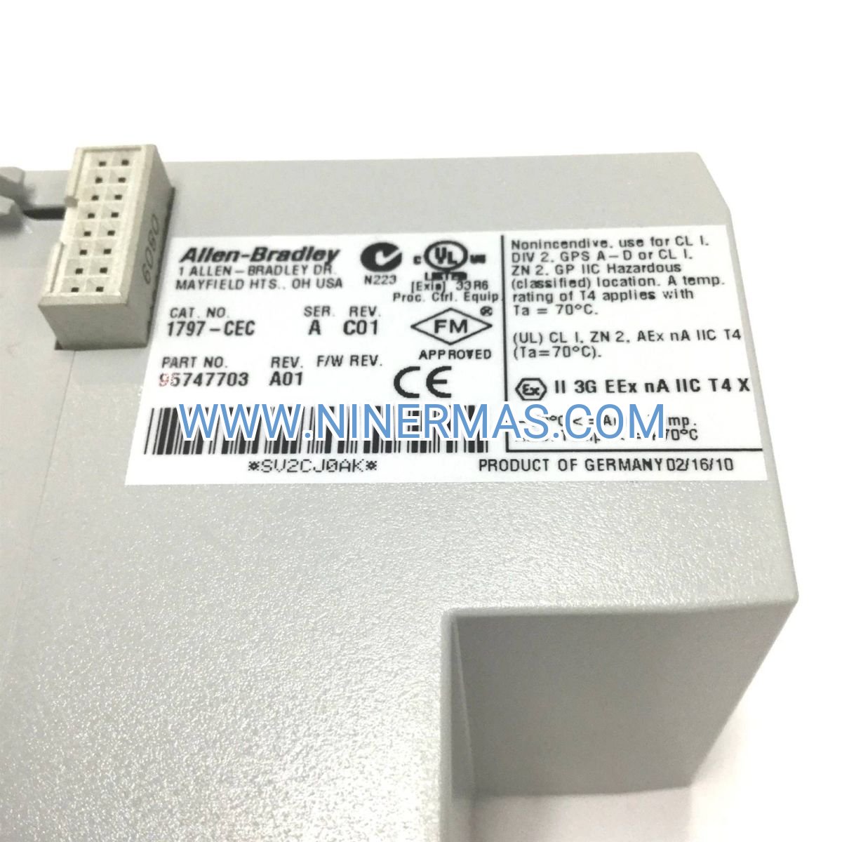
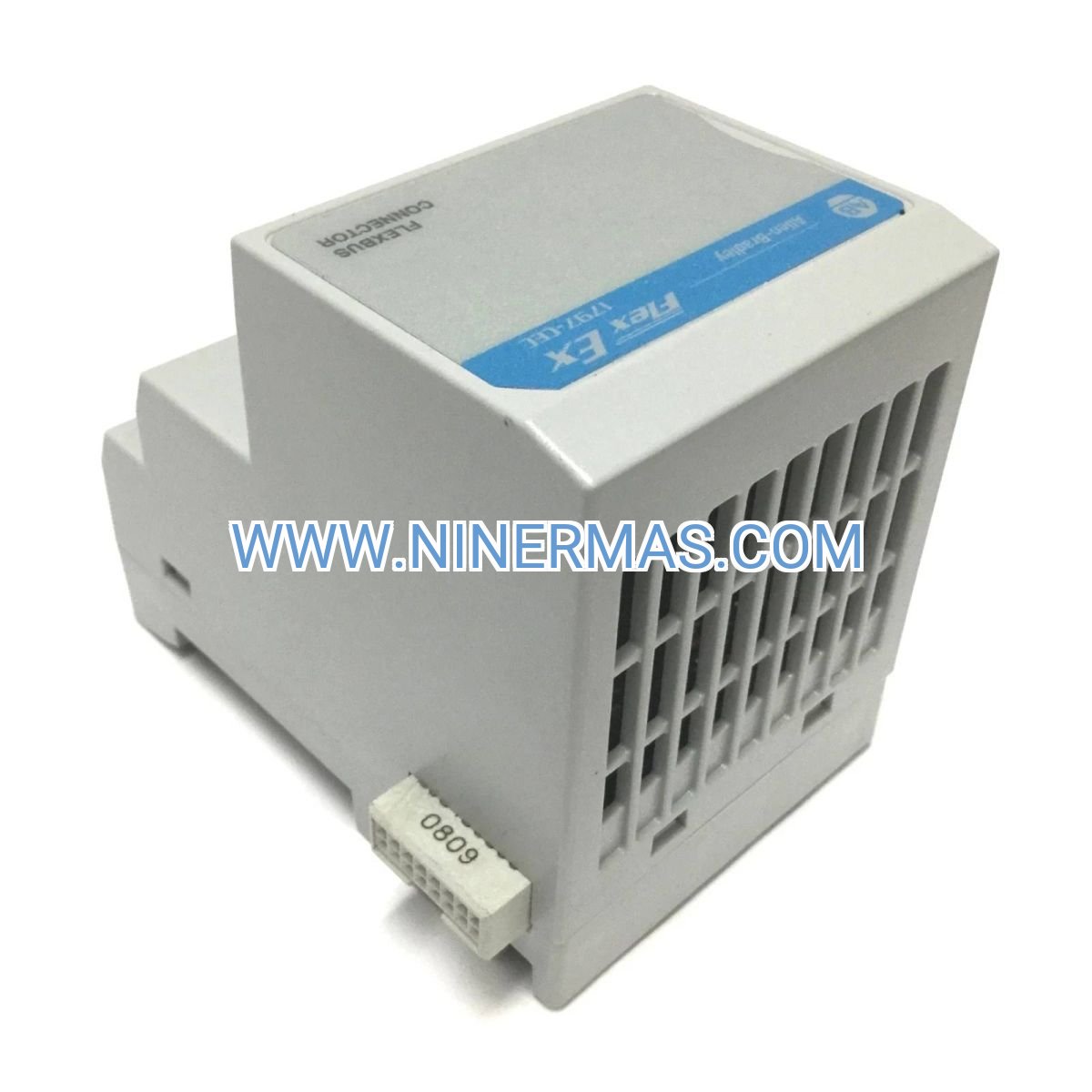
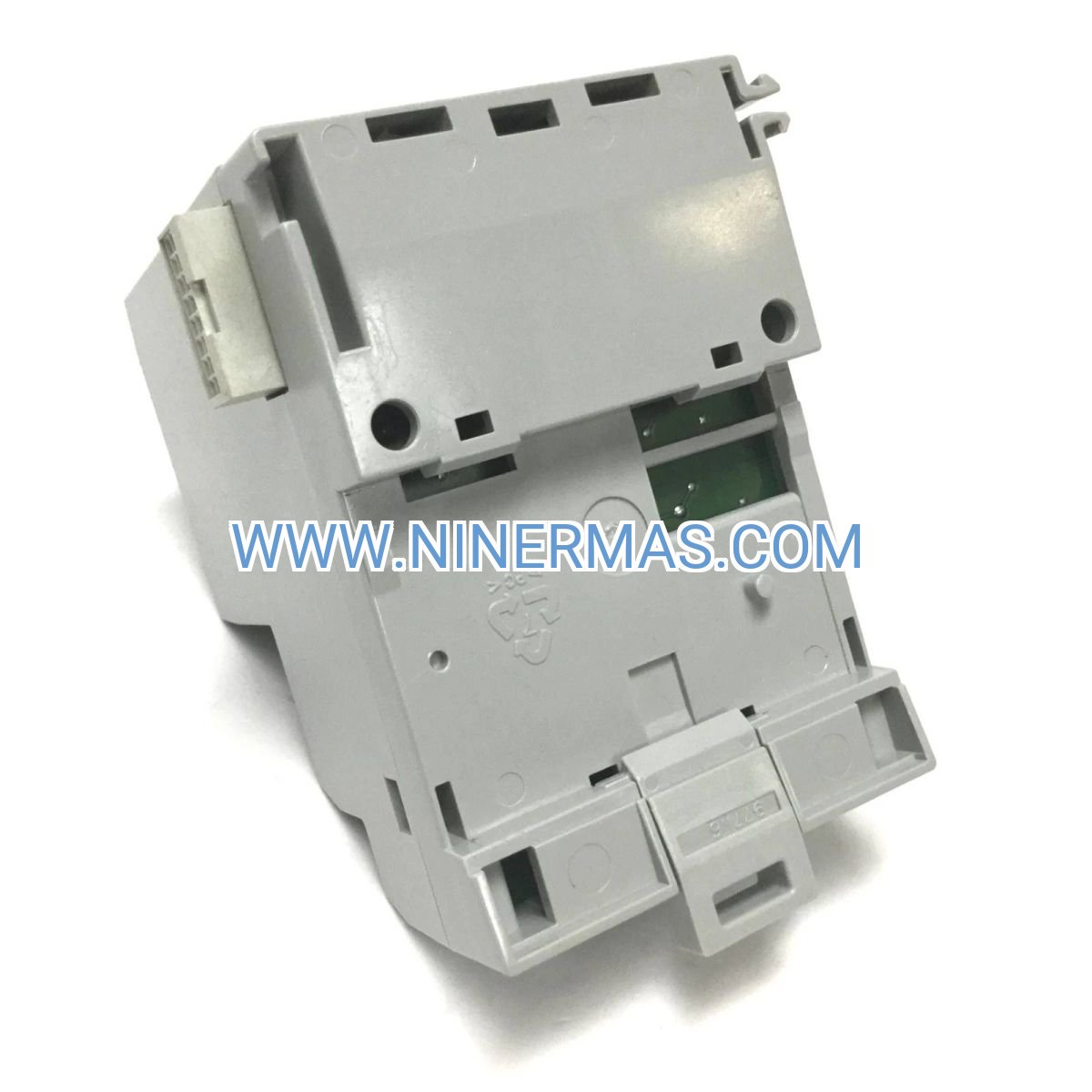
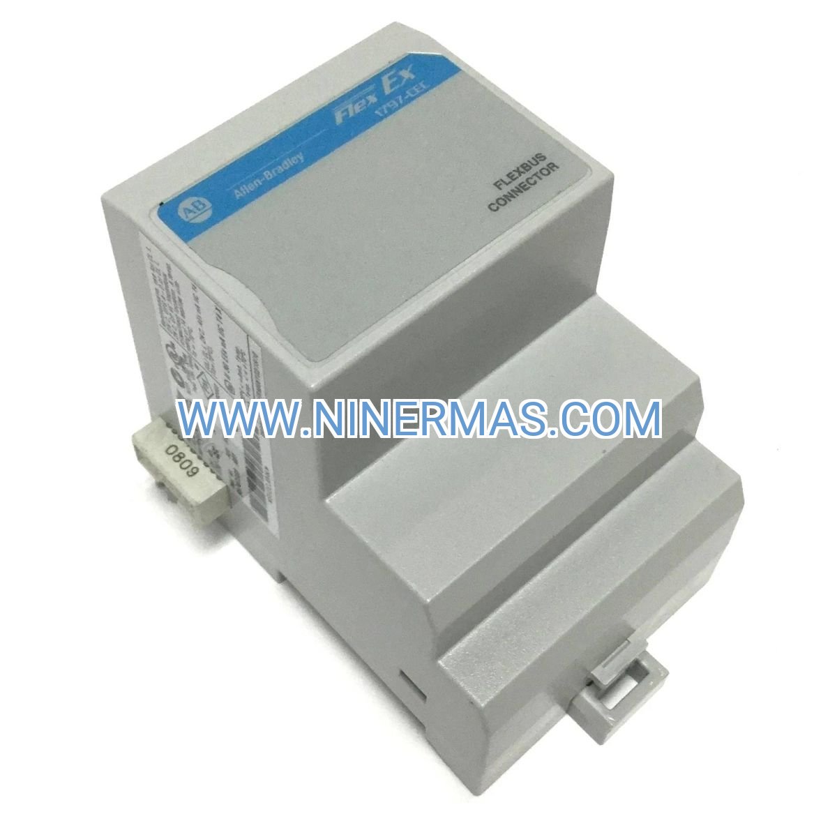
Allen-Bradley 1797-CEC Flex Ex I/O Bus Connector Module (Intrinsically Safe Control Solution)
The Allen-Bradley 1797-CEC Flex Ex I/O Bus Connector Module is a specialized industrial control component designed for intrinsically safe applications in hazardous environments. Through certified explosion-proof design and advanced signal isolation technology, it enables reliable data communication and power distribution in Zone 2/Division 2 classified locations. This module ensures safe, continuous operation in potentially explosive atmospheres while maintaining high-speed I/O connectivity.
Ideal for oil & gas facilities, chemical processing plants, pharmaceutical manufacturing, grain handling systems, and paint spray booths—environments where flammable gases, vapors, or combustible dust may be present. It addresses critical challenges including explosion risk mitigation, signal integrity in harsh conditions, compliance with safety certifications (ATEX, IECEx, CSA), and the need for hot-swappable maintenance without system shutdown.
Featuring factory-calibrated intrinsic safety barriers, UL/CSA/ATEX certified construction, and seamless integration with Flex Ex distributed I/O systems, this connector module delivers proven reliability for design engineers, system integrators, EPC contractors, and plant maintenance teams. Contact our application engineers for hazardous area classification review, wiring diagrams, and certified documentation packages.
Core Features & Advantages
- Intrinsically Safe Design
Certified for use in Zone 2/Division 2 hazardous locations with built-in energy-limiting circuits that prevent ignition sources, ensuring compliance with IEC 60079-11 and NEC 505/506 standards for explosive atmosphere protection. - Seamless Flex Ex System Integration
Direct plug-in compatibility with Allen-Bradley 1797 Flex Ex I/O modules, supporting up to 8 I/O points per connector with automatic addressing and hot-swap capability for minimal downtime during maintenance. - Robust Environmental Protection
IP20-rated enclosure with conformal coating protects against moisture, dust, and chemical exposure; operating temperature range of -20°C to +60°C suits demanding industrial environments including offshore platforms and outdoor installations. - Diagnostic & Fault Indication
Integrated LED status indicators provide real-time visibility of power, communication, and fault conditions; supports DeviceNet/EtherNet/IP network diagnostics for predictive maintenance and rapid troubleshooting. - Simplified Installation & Wiring
Tool-free DIN rail mounting with removable terminal blocks and color-coded wiring labels reduce installation time by up to 40%; comprehensive documentation includes loop drawings and intrinsic safety entity parameters. - Global Safety Certifications
Factory-certified to ATEX, IECEx, CSA C22.2, UL 508, and FM standards, eliminating costly field certification processes and ensuring acceptance by AHJs (Authorities Having Jurisdiction) worldwide.
Typical Application Scenarios
This connector module is engineered for environments requiring intrinsic safety compliance and reliable I/O connectivity, particularly in:
- Oil & Gas Production Facilities
Wellhead monitoring, separator control, and pipeline instrumentation in Zone 2 classified areas; supports integration with pressure transmitters, flow meters, and valve actuators in potentially explosive atmospheres. - Chemical & Petrochemical Plants
Reactor monitoring, batch process control, and emergency shutdown systems where flammable vapors may be present; ensures safe signal transmission from field devices to control rooms without spark risk. - Pharmaceutical Manufacturing
Solvent handling areas, spray drying systems, and cleanroom interfaces requiring both intrinsic safety and contamination control; compatible with stainless steel enclosures and wash-down environments. - Grain Handling & Food Processing
Dust collection systems, pneumatic conveying, and silo level monitoring in combustible dust environments (Class II Division 2); prevents ignition sources near grain elevators, flour mills, and sugar refineries. - Paint & Coating Operations
Spray booth controls, solvent vapor monitoring, and ventilation interlocks in automotive, aerospace, and furniture finishing facilities; meets NFPA 33 requirements for flammable finishing operations.
Technical Parameters & Selection Guide
To facilitate engineering design and system specification, we provide standardized electrical, mechanical, and environmental parameters. Custom configurations available for unique hazardous area classifications or I/O requirements.
| Parameter | Specification |
|---|---|
| Catalog Number | 1797-CEC |
| Product Series | Flex Ex Intrinsically Safe I/O |
| Hazardous Location Rating | Class I Division 2 Groups A, B, C, D / Zone 2 IIC T4 |
| I/O Capacity | Up to 8 digital or 4 analog channels per connector |
| Power Supply | 24V DC ±20% (intrinsically safe limited) |
| Current Consumption | Max 150mA @ 24V DC (from safe area supply) |
| Communication Protocol | DeviceNet / EtherNet/IP (via adapter module) |
| Mounting | 35mm DIN rail (EN 50022) |
| Enclosure Rating | IP20 (NEMA Type 1 equivalent) |
| Operating Temperature | -20°C to +60°C (-4°F to +140°F) |
| Storage Temperature | -40°C to +85°C (-40°F to +185°F) |
| Relative Humidity | 5% to 95% non-condensing |
| Dimensions (H×W×D) | 118mm × 35mm × 114mm (4.65" × 1.38" × 4.49") |
| Weight | Approx. 0.2 kg (0.44 lbs) |
| Certifications | UL, CSA, ATEX, IECEx, FM, CE |
Selection Recommendations: When specifying this module, consider: (1) Hazardous area classification (Zone/Division and Gas Group), (2) Required I/O point count and signal types (digital/analog, input/output), (3) Network architecture (DeviceNet vs. EtherNet/IP), (4) Environmental conditions (temperature extremes, vibration, chemical exposure), (5) Enclosure requirements (panel-mount vs. field-mount with additional protection). For application-specific guidance, provide your P&ID, I/O list, and area classification drawings—our certified engineers will recommend the optimal configuration and provide intrinsic safety calculation worksheets.
Extended Functionality & System Integration
- Redundant Power Input: Optional dual 24V DC supply configuration with automatic failover ensures continuous operation in critical safety systems.
- Modular Expansion: Daisy-chain up to 63 Flex Ex modules on a single network segment, supporting distributed architectures across large process areas.
- HART Protocol Support: Transparent pass-through of HART communication enables access to smart transmitter diagnostics and configuration without additional gateways.
- SIL 2 Capability: When configured per TÜV-certified safety manual, suitable for Safety Instrumented Systems (SIS) applications up to SIL 2 per IEC 61508/61511.
- Studio 5000 Integration: Pre-built Add-On Profiles (AOP) and Electronic Data Sheets (EDS) streamline programming in Logix Designer with automatic I/O mapping and diagnostics.
Delivery, Service & Quality Assurance
Lead Time: Standard catalog items ship within 3-5 business days from regional distribution centers; custom-configured assemblies require 10-15 business days for factory testing and certification documentation.
Warranty: 12-month manufacturer's warranty covering defects in materials and workmanship; extended service agreements available for critical applications requiring 24/7 support.
Technical Support: Complimentary pre-sale application engineering assistance including hazardous area classification review, loop diagram verification, and intrinsic safety calculations. Post-sale support includes remote diagnostics via TeamViewer/Webex and on-site commissioning services (subject to geographic availability and project scope).
Documentation Package: Each module ships with: (1) Installation Instructions (Publication 1797-IN001), (2) Intrinsic Safety Entity Parameters, (3) Wiring Diagrams with Terminal Assignments, (4) Certification Certificates (ATEX/IECEx/CSA), (5) Dimensional Drawings (DXF/PDF), (6) Studio 5000 Add-On Profile. Additional resources including 3D CAD models (STEP/IGES) and Revit families available via Product Compatibility & Download Center.
Frequently Asked Questions (FAQ)
Q: How does the 1797-CEC Flex Ex I/O Bus Connector integrate with existing non-intrinsically safe control systems?
A: The 1797-CEC acts as a bridge between safe area controllers (e.g., CompactLogix, ControlLogix) and hazardous area field devices. It connects to a Flex Ex adapter module (1797-AENTR or 1797-DN) located in the safe area via intrinsically safe fieldbus cable, then distributes power and signals to I/O modules in the hazardous zone. Intrinsic safety barriers are built into the connector, eliminating the need for external zener barrier panels. Verify that total system entity parameters (Voc, Isc, Ca, La) remain within certified limits per control drawing.
Q: What is the maximum number of I/O modules that can be connected to a single 1797-CEC connector?
A: Each 1797-CEC connector supports one Flex Ex I/O module (digital or analog). To expand capacity, daisy-chain additional connectors using the integrated bus interface—up to 8 modules per Flex Ex adapter and 63 modules per network segment. Total I/O count is limited by adapter capacity (e.g., 1797-AENTR supports 63 modules) and network power budget (calculate using Flex Ex Power Supply Selection Tool, publication 1797-PP001).
Q: What energy savings or operational benefits can be expected from using intrinsically safe I/O versus traditional barrier-based systems?
A: While intrinsic safety focuses on explosion prevention rather than energy efficiency, the 1797-CEC system reduces installation costs by 25-40% compared to traditional zener barrier panels through: (1) Elimination of barrier racks and associated wiring, (2) Reduced panel space (no separate safe area marshalling), (3) Simplified loop checking (pre-certified entity parameters), (4) Lower maintenance (no barrier fuse replacements). Operational benefits include hot-swap module replacement without system shutdown, reducing unplanned downtime by up to 60% in critical processes.
Q: What are the environmental and installation requirements for the 1797-CEC connector module?
A: The module is rated IP20 (open-type enclosure) and must be installed inside a suitable panel or junction box providing minimum IP54 protection in industrial environments. Operating temperature range is -20°C to +60°C with 5-95% RH non-condensing. For outdoor or wash-down applications, specify NEMA 4X/IP66 stainless steel enclosures with thermostat-controlled heating/cooling. Mounting requires standard 35mm DIN rail per EN 50022; maintain 50mm clearance above and below for convection cooling. Avoid installation near high-frequency VFDs or welding equipment—minimum 300mm separation recommended to prevent EMI.
Q: Does the 1797-CEC support remote monitoring, data logging, or integration with SCADA/MES systems?
A: Yes, when connected via 1797-AENTR EtherNet/IP adapter, the system supports full integration with FactoryTalk View SE, Ignition SCADA, Wonderware, and other OPC UA/DA-compliant platforms. Real-time I/O data, diagnostic counters, and fault logs are accessible via standard CIP (Common Industrial Protocol) objects. For historian integration, use FactoryTalk Historian or OSIsoft PI with native Logix drivers. The module also supports SNMP traps and email alerts for critical faults when configured through the network adapter's embedded web server. HART-enabled analog modules allow pass-through access to smart transmitter parameters for predictive maintenance analytics.
Q: Is the 1797-CEC certified for use in global markets, and what documentation is required for AHJ approval?
A: The module carries UL 508 (USA), CSA C22.2 No. 142 (Canada), ATEX II 3G Ex nA IIC T4 Gc (Europe), IECEx (international), and FM (Factory Mutual) certifications. For project approval, provide: (1) Manufacturer's Certificate of Conformity, (2) Control Drawing showing entity parameters, (3) Installation Instructions (Publication 1797-IN001), (4) Area Classification Drawings (by others, showing Zone/Division boundaries). Most AHJs accept Allen-Bradley's pre-certified system approach without additional third-party inspection, but confirm local requirements—some jurisdictions (e.g., offshore platforms under NORSOK) may require additional documentation or witness testing.
Request Engineering Support & Quotation
To receive a detailed system configuration proposal, certified documentation package, or project-specific pricing, please provide the following information to our application engineering team:
- Project name and end-user facility location
- Hazardous area classification (Zone/Division, Gas Group, Temperature Class)
- I/O requirements (quantity and type: DI, DO, AI, AO; signal ranges; HART required?)
- Network architecture (DeviceNet, EtherNet/IP, or standalone)
- Environmental conditions (temperature range, enclosure rating, vibration/shock)
- Delivery schedule and installation support requirements
Our certified engineers will provide one-on-one consultation including hazardous area suitability assessment, intrinsic safety calculations, wiring diagrams, and compliance documentation within 48 hours.
© 2026 NINERMAS COMPANY LIMITED. All rights reserved.
Original Source: https://ninermas.com
Contact: sale@ninermas.com | +0086 187 5021 5667


Contact Info
-
Address:22 / F, South Wo Hang building, 148 Wing Lok Street, Sheung Wan, Western District, Hong Kong
-
Phone:+8618750215667
-
Email: