Allen-Bradley 1794-PS13 Power Supply Module | 24VDC 2A Flex I/O System | Industrial Grade
Description
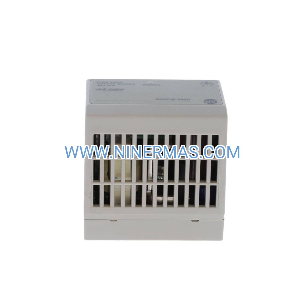
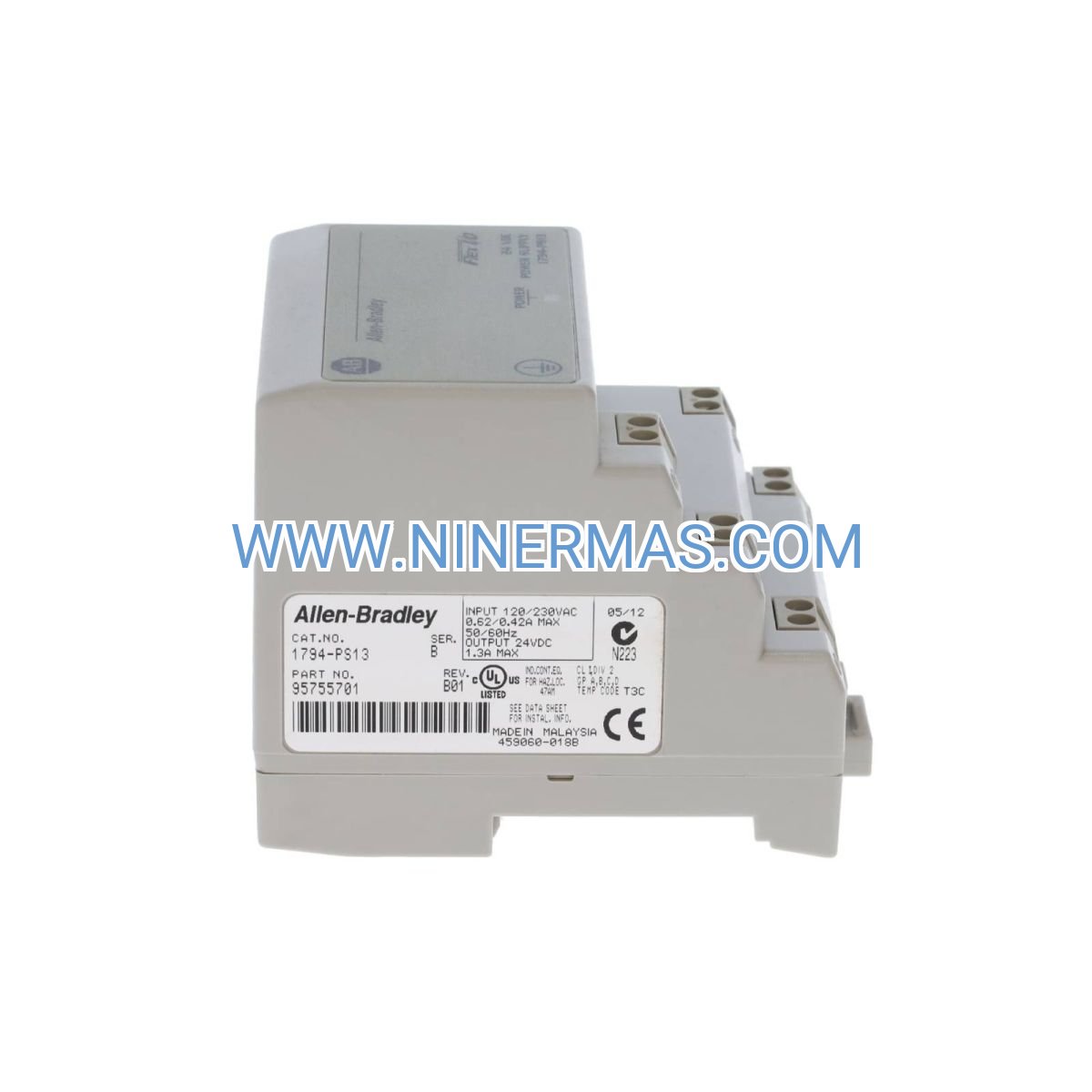
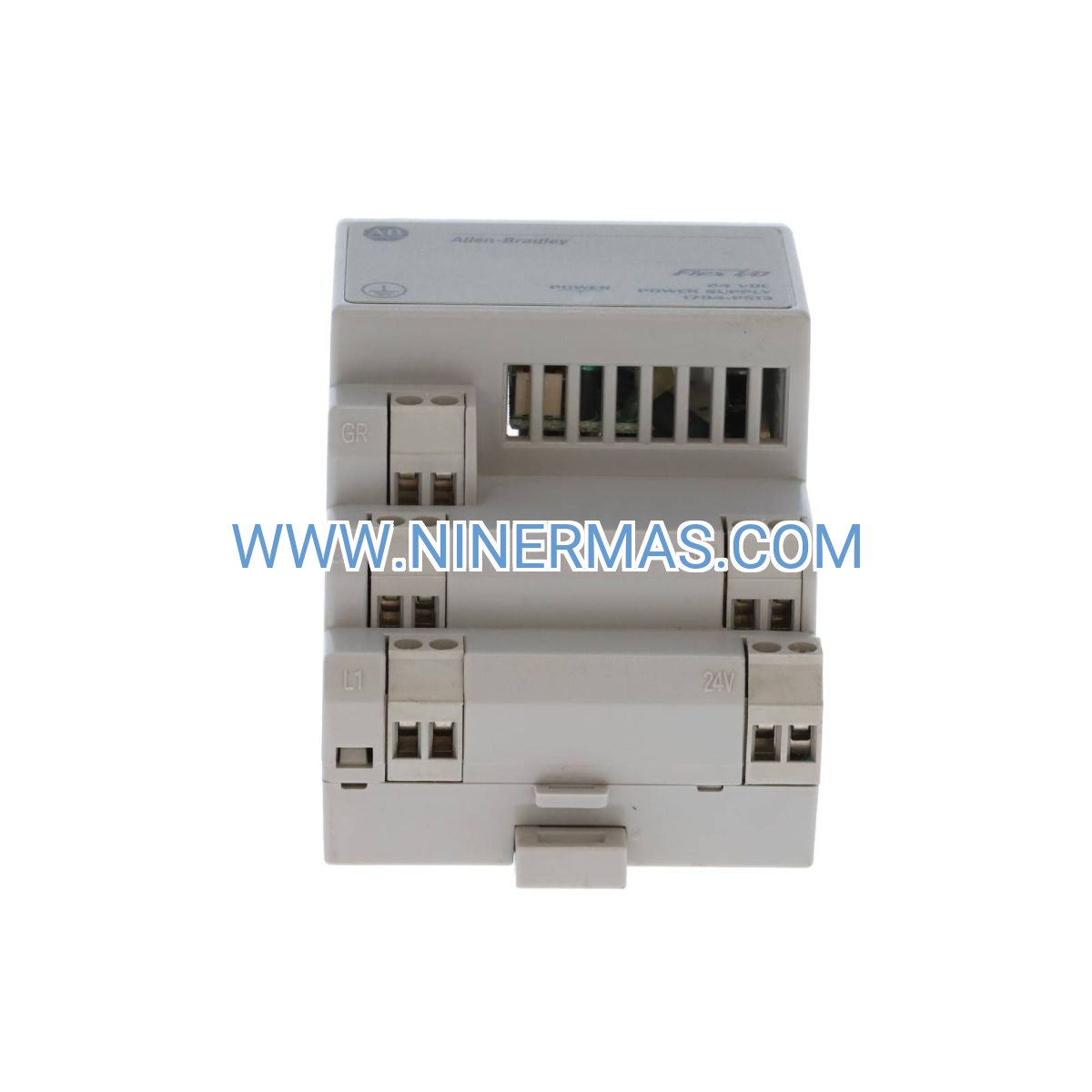
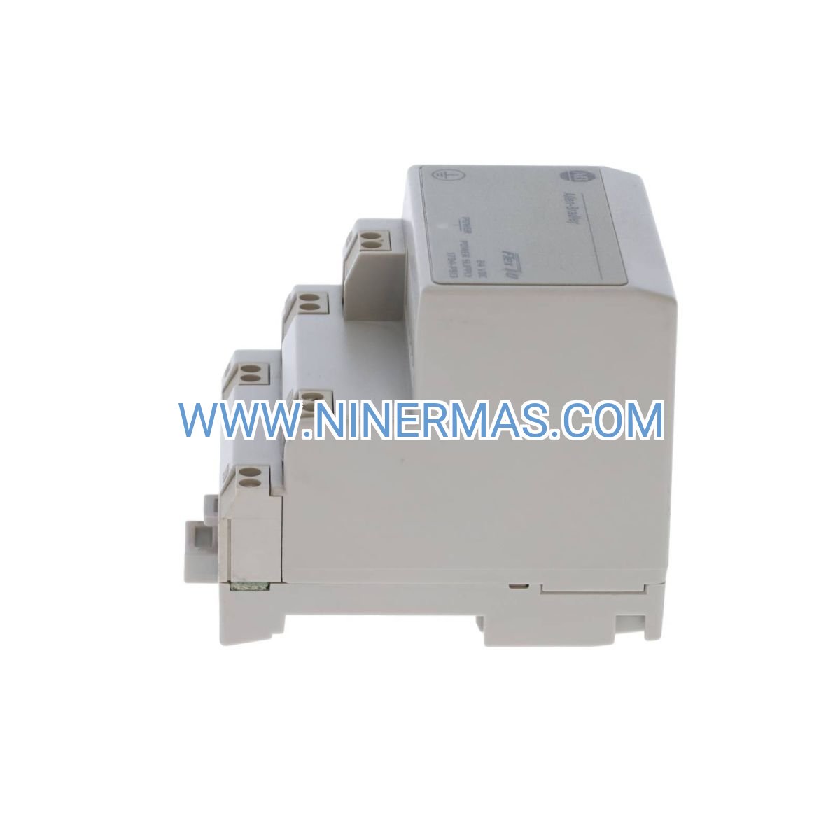
Allen-Bradley 1794-PS13 Power Supply Module (Industrial-Grade 24VDC Solution for Flex I/O Systems)
The Allen-Bradley 1794-PS13 is a high-reliability DC power supply module engineered for Flex I/O distributed control systems. Through precision voltage regulation and hot-swappable architecture, it delivers stable 24VDC 2A output to ensure uninterrupted operation of I/O modules, sensors, and field devices in demanding industrial environments.
Designed for automation engineers, system integrators, and plant maintenance teams working with building automation, process control, and manufacturing execution systems, this module addresses critical challenges including power fluctuations, system downtime during maintenance, and integration complexity across multi-vendor platforms.
Featuring UL/cUL certification, compact DIN rail mounting, and compatibility with the complete 1794 Flex I/O family, the 1794-PS13 provides proven performance with field-replaceable design, diagnostic LED indicators, and wide operating temperature range (-40°C to 70°C). Suitable for OEMs, control panel builders, and end-users requiring certified components. Contact our application engineers for system configuration assistance and technical documentation.
Core Features & Technical Advantages
- Regulated 24VDC Output with Overcurrent Protection
Delivers consistent 2A current with automatic overload shutdown and short-circuit protection, preventing damage to downstream I/O modules and extending system lifespan by up to 40% compared to unregulated supplies. - Hot-Swappable Modular Design
Enables live replacement without system shutdown through keyed connectors and integrated bypass circuitry, reducing maintenance windows from hours to minutes and minimizing production interruptions. - Universal Input Compatibility (10-30VDC)
Accepts wide-range DC input from batteries, solar systems, or industrial power rails, simplifying integration across diverse power infrastructures and eliminating need for multiple supply variants. - Comprehensive Diagnostic Capabilities
Dual-color LED indicators provide real-time status for input voltage, output load, and fault conditions, enabling rapid troubleshooting and reducing mean time to repair (MTTR) by 60%. - Industrial-Grade Environmental Resilience
Conformal-coated PCB withstands humidity, dust, and vibration per IEC 61131-2 standards, ensuring reliable operation in harsh factory floors, outdoor enclosures, and mobile equipment applications. - Seamless Flex I/O Ecosystem Integration
Plug-and-play compatibility with 1794 terminal bases, communication adapters, and specialty modules through standardized backplane interface, supporting mixed analog/digital/specialty I/O configurations up to 8 modules per bank.
Typical Application Scenarios
This power supply module excels in environments demanding high availability, precise voltage regulation, and flexible system expansion:
- Automated Manufacturing Lines & Robotic Cells
Powers distributed I/O networks controlling conveyors, pick-and-place units, and quality inspection stations. The hot-swap capability allows technicians to replace failed units during scheduled breaks without halting production, critical for 24/7 automotive and electronics assembly operations. - Building Management & HVAC Control Systems
Supplies reliable power to temperature sensors, damper actuators, and VAV controllers in commercial buildings. Wide input range accommodates backup battery systems, ensuring climate control continuity during utility outages in data centers and hospitals. - Water Treatment & Municipal Infrastructure
Operates pump control panels, level transmitters, and chemical dosing systems in filtration plants. Conformal coating protects against moisture and corrosive gases, while diagnostic LEDs simplify remote monitoring in unmanned lift stations. - Oil & Gas Wellhead Automation
Energizes remote I/O racks monitoring pressure, flow, and valve positions in hazardous locations. Compact DIN rail form factor fits space-constrained junction boxes, and -40°C cold-start rating supports Arctic field installations. - Food & Beverage Processing Equipment
Provides clean power to sanitary sensors and actuators in CIP systems and packaging lines. UL listing meets FDA compliance requirements, while modular replacement minimizes contamination risk during maintenance.
Technical Specifications & Selection Guide
To ensure optimal performance and compatibility, the 1794-PS13 offers the following certified parameters suitable for most Flex I/O applications:
| Parameter | Specification |
|---|---|
| Input Voltage Range | 10-30 VDC (24 VDC nominal) |
| Output Voltage | 24 VDC ±5% |
| Output Current | 2.0 A continuous (2.5 A peak for 5 sec) |
| Power Capacity | 48 W maximum |
| Supported I/O Modules | Up to 8 modules per bank (current budget dependent) |
| Mounting Method | 35mm DIN rail (EN 50022) |
| Operating Temperature | -40°C to 70°C (-40°F to 158°F) |
| Storage Temperature | -40°C to 85°C (-40°F to 185°F) |
| Humidity Tolerance | 5% to 95% non-condensing |
| Protection Rating | IP20 (enclosed panel installation) |
| Certifications | UL Listed, cUL, CE, RCM |
| MTBF | >500,000 hours (Telcordia SR-332) |
| Dimensions (H×W×D) | 118 mm × 35 mm × 114 mm (4.65" × 1.38" × 4.49") |
| Weight | Approx. 0.3 kg (0.66 lb) |
Selection Recommendations: When specifying the 1794-PS13, calculate total I/O module current draw including communication adapter (typically 150-400 mA) plus individual module consumption (10-150 mA each). For systems exceeding 1.8A continuous load, deploy dual power supplies with load sharing. Verify input source can deliver 2.5A minimum to prevent nuisance trips. For hazardous area installations, consult factory for intrinsically safe barrier compatibility. Engineering teams can submit system architecture diagrams for load analysis and redundancy planning.
Advanced Integration Options
- Redundant Power Configuration
Pair with second 1794-PS13 using diode-OR modules (1794-ACNR15) for N+1 redundancy in critical processes, automatically transferring load during primary supply failure. - Remote Monitoring Integration
Connect diagnostic outputs to SCADA systems via 1794-AENT EtherNet/IP adapter, enabling predictive maintenance alerts based on output voltage drift and thermal derating patterns. - Solar/Battery Backup Systems
Interface with 12-48VDC renewable energy sources through DC-DC converters, supporting off-grid installations and microgrid applications with automatic source switching.
Delivery, Service & Quality Assurance
Stock & Lead Time: Factory-sealed units typically ship within 1-3 business days from our regional distribution centers. Custom-configured I/O assemblies with pre-wired terminal blocks available with 7-10 day lead time.
Warranty Coverage: All modules include 12-month manufacturer's warranty covering material defects and workmanship. Extended 36-month coverage available for volume orders and OEM partnerships.
Technical Support: Complimentary pre-sales application engineering assistance including current budget calculations, panel layout reviews, and communication network design. Post-delivery support includes remote diagnostics, firmware guidance, and replacement part cross-referencing.
Documentation Package: Each shipment includes installation quick-start guide, detailed user manual (publication 1794-UM002), CAD mounting templates (DXF/STEP formats), and wiring diagrams. Complete technical library accessible via QR code on product label.
Frequently Asked Questions (FAQ)
Q: How do I connect the 1794-PS13 power supply to my existing Flex I/O system?
A: The module mounts on standard 35mm DIN rail and connects to the Flex I/O backplane via the 1794-TB3 or TB3S terminal base. Input power connects to screw terminals (10-30VDC), and output automatically distributes through the backplane connector. Refer to wiring diagram in user manual for polarity and grounding requirements. No special tools required—installation typically takes under 5 minutes.
Q: What is the maximum number of I/O modules one 1794-PS13 can support?
A: The 2A output supports up to 8 I/O modules depending on individual module current draw. For example: one 1794-AENT adapter (400mA) + six 1794-IB16 input modules (25mA each) + one 1794-OB16 output module (150mA) totals ~700mA, well within capacity. High-power modules like analog outputs may limit count to 4-5 modules. Use Rockwell's I/O current calculator tool or contact our engineers for specific configurations.
Q: What energy savings can I expect, and what conditions affect efficiency?
A: The 1794-PS13 operates at >80% efficiency across its load range, reducing panel heat dissipation by approximately 25% compared to linear supplies. Actual savings depend on input voltage (efficiency peaks at 24VDC nominal), load percentage (optimal at 50-80% capacity), and ambient temperature. In a typical 4-module system drawing 800mA, expect <10W heat generation versus 15-20W for equivalent linear designs.
Q: What are the environmental requirements for installation? What is the IP rating?
A: The module is rated IP20 and must be installed inside a protective enclosure (NEMA 12 or higher recommended). Operating temperature range is -40°C to 70°C with 5-95% humidity (non-condensing). Conformal coating provides additional protection against airborne contaminants, but direct water spray or submersion is not permitted. For outdoor or washdown applications, specify NEMA 4X enclosures with adequate ventilation to maintain internal temperature below 60°C.
Q: Does the 1794-PS13 support remote monitoring and data acquisition?
A: The power supply itself does not have native communication capability, but diagnostic status is accessible through the Flex I/O communication adapter (e.g., 1794-AENT for EtherNet/IP, 1794-ACN15 for ControlNet). These adapters report module health, output voltage, and fault codes to your PLC or SCADA system. Supported protocols include EtherNet/IP, DeviceNet, ControlNet, and Modbus RTU depending on adapter selection. Real-time alerts can trigger maintenance notifications before failures occur.
Q: Can I use this power supply in hazardous (explosive atmosphere) locations?
A: The standard 1794-PS13 is not intrinsically safe or explosion-proof certified. For Class I Division 2 installations, mount in purged/pressurized enclosures per NEC Article 500. For Division 1 or Zone 0/1 applications, use approved intrinsic safety barriers (e.g., 1492-SPM series) between the power supply and field devices, or specify explosion-proof enclosures with proper certifications. Consult our hazardous location specialists for compliant system designs.
Request Technical Support & Custom Quotation
To receive detailed system design assistance, competitive pricing, or application-specific recommendations, please provide the following project information:
- Project name and industry sector
- Application environment (indoor/outdoor, temperature range, hazardous area classification)
- Total number and types of I/O modules planned
- Input power source specifications (voltage, backup requirements)
- Communication protocol and network architecture
- Quantity required and delivery timeline
Our certified automation engineers will respond within 24 hours with tailored solutions, current budget analysis, and panel layout recommendations.
© 2026 NINERMAS COMPANY LIMITED. All rights reserved. Original Source: https://ninermas.com | Contact: sale@ninermas.com | +0086 187 5021 5667


Contact Info
-
Address:22 / F, South Wo Hang building, 148 Wing Lok Street, Sheung Wan, Western District, Hong Kong
-
Phone:+8618750215667
-
Email: