Allen-Bradley 1771-RTP4 Remote Termination Panel | PLC-5 Analog I/O Wiring Solution
Description
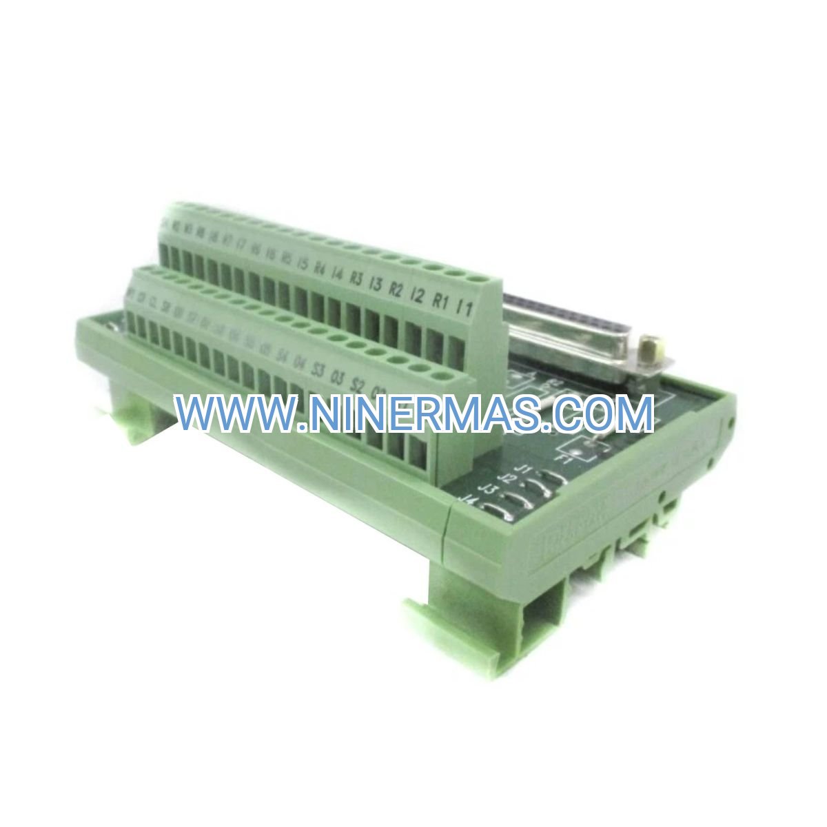
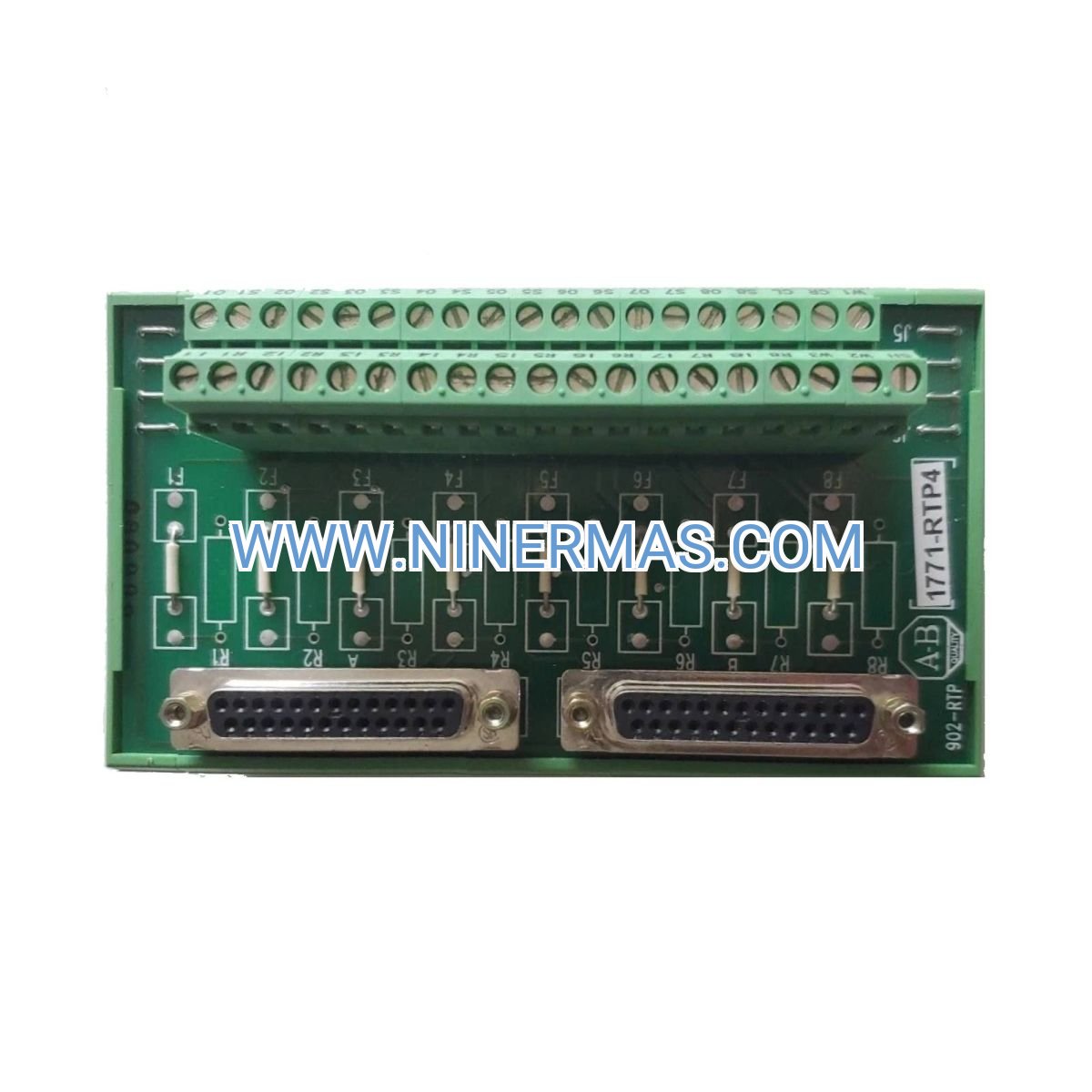
Allen-Bradley 1771-RTP4 Remote Termination Panel (Industrial-Grade Field Wiring Solution)
The Allen-Bradley 1771-RTP4 Remote Termination Panel is a professional field wiring interface designed specifically for PLC-5 analog I/O systems. Through standardized terminal block design and modular connection architecture, it enables rapid, reliable field signal termination for 4-20mA current loops and 0-10VDC voltage signals, significantly reducing installation time and wiring errors.
Ideal for industrial automation applications including process control systems, SCADA installations, manufacturing plants, water treatment facilities, and building automation projects. This termination panel solves common challenges such as complex field wiring, difficult troubleshooting, inconsistent installation quality, and time-consuming commissioning processes.
With proven reliability in harsh industrial environments, standardized wiring configurations, and compatibility with Allen-Bradley PLC-5 analog I/O modules, the 1771-RTP4 is trusted by system integrators, control panel builders, OEM manufacturers, and plant maintenance teams worldwide. Contact our application engineers for wiring diagrams, technical specifications, and project-specific recommendations.
Core Features & Technical Advantages
- Simplified Field Wiring Architecture
Pre-configured terminal blocks with clearly labeled connection points eliminate wiring confusion, reduce installation time by up to 40%, and minimize human error during commissioning. - Universal Analog Signal Compatibility
Supports industry-standard 4-20mA current loop and 0-10VDC voltage signals, ensuring seamless integration with sensors, transmitters, actuators, and field instruments from multiple manufacturers. - Robust Industrial Construction
Built with high-grade terminal blocks, reinforced mounting rails, and corrosion-resistant materials to withstand vibration, temperature fluctuations, electrical noise, and demanding factory floor conditions. - Enhanced Troubleshooting Efficiency
Individual terminal access points and organized wire routing enable rapid fault diagnosis, signal testing, and maintenance without disrupting adjacent circuits or system operation. - Flexible Mounting Options
Compatible with standard DIN rail and panel mounting configurations, allowing installation in control cabinets, junction boxes, or field enclosures based on project requirements. - Comprehensive Protection Features
Integrated strain relief, wire management channels, and proper grounding provisions protect signal integrity, reduce electromagnetic interference, and extend system lifespan.
Typical Application Scenarios
The 1771-RTP4 termination panel is engineered for applications demanding reliable analog signal interface, organized field wiring, and long-term operational stability:
- Process Control & Manufacturing Automation
Connects temperature sensors, pressure transmitters, flow meters, and level sensors to PLC-5 analog input modules in chemical plants, food processing facilities, pharmaceutical production lines, and discrete manufacturing operations. - Water & Wastewater Treatment Systems
Interfaces pH sensors, turbidity meters, chlorine analyzers, and flow transmitters with PLC-5 controllers for municipal water treatment plants, industrial wastewater facilities, and irrigation control systems. - HVAC & Building Automation
Terminates temperature probes, humidity sensors, pressure transducers, and damper actuators in commercial buildings, data centers, hospitals, and institutional facilities requiring precise environmental control. - Oil & Gas Production Facilities
Provides field wiring interface for pressure transmitters, temperature sensors, and flow meters in upstream production, midstream pipeline monitoring, and downstream refining applications. - Power Generation & Distribution
Connects analog instrumentation for generator monitoring, transformer temperature sensing, switchgear protection, and substation automation in utility and industrial power systems.
Technical Specifications & Selection Guide
To ensure optimal system performance and compatibility, the 1771-RTP4 is designed with the following technical parameters:
| Compatible I/O Modules | Allen-Bradley PLC-5 Analog Input/Output Modules (1771-IF series, 1771-OF series) |
| Signal Types Supported | 4-20mA current loop, 0-10VDC voltage signals |
| Number of Channels | 4 analog channels per panel |
| Terminal Block Type | Screw-clamp terminals, accepts 12-22 AWG wire |
| Mounting Method | DIN rail or panel mount (hardware included) |
| Operating Temperature | 0°C to 60°C (32°F to 140°F) |
| Humidity Range | 5% to 95% non-condensing |
| Enclosure Rating | Suitable for NEMA Type 1 / IP20 environments |
| Dimensions (H×W×D) | Approximately 120mm × 80mm × 45mm |
| Compliance Standards | UL Listed, CE marked, RoHS compliant |
Selection Recommendations: When specifying the 1771-RTP4, consider the number of analog I/O points required, field signal types (current vs. voltage), wire gauge and routing distance, environmental conditions (temperature, humidity, vibration), and control cabinet space constraints. For systems requiring more than 4 channels, multiple panels can be installed side-by-side. Our application engineers can assist with panel layout, wiring diagrams, and bill of materials preparation—simply provide your I/O list, signal specifications, and installation environment details.
Extended Capabilities & System Integration
- Modular Expansion: Multiple 1771-RTP4 panels can be combined to support large-scale I/O systems with dozens or hundreds of analog points, maintaining consistent wiring standards across the entire installation.
- Documentation & Labeling: Each terminal position is clearly marked and corresponds to standard Allen-Bradley I/O addressing, simplifying as-built documentation, future modifications, and operator training.
- Retrofit & Upgrade Projects: Ideal for modernizing legacy PLC-5 systems, replacing damaged wiring infrastructure, or improving maintainability of existing installations without complete system replacement.
- Quality Assurance: Factory-tested components and proven design ensure reliable operation in mission-critical applications where downtime costs are high and system availability is paramount.
Delivery, Service & Technical Support
Lead Time: Standard catalog items typically ship within 1-3 business days from stock. For bulk orders or project-specific configurations, delivery time is 5-10 business days depending on quantity and customization requirements.
Warranty Coverage: All 1771-RTP4 panels include a minimum 12-month manufacturer warranty covering defects in materials and workmanship. Extended warranty options available for critical applications.
Technical Documentation: Each unit ships with installation instructions, wiring diagrams, dimensional drawings, and compatibility charts. CAD files, 3D models, and detailed specifications available upon request for design and engineering teams.
Application Support: Our technical team provides pre-sales consultation, wiring layout review, troubleshooting assistance, and post-installation support via phone, email, and remote diagnostics (subject to regional availability).
Training Resources: Installation guides, best practice documents, and video tutorials available to ensure proper installation, commissioning, and long-term reliability.
Frequently Asked Questions (FAQ)
Q: How does the 1771-RTP4 remote termination panel connect to PLC-5 analog I/O modules?
A: The panel provides screw-terminal field wiring points that connect via shielded cable to the corresponding Allen-Bradley 1771 analog I/O module installed in the PLC-5 chassis. Wiring diagrams specify pin-to-terminal correspondence, shield grounding, and cable specifications (typically 18-22 AWG shielded twisted pair).
Q: Can one termination panel support both current and voltage signals simultaneously?
A: Yes, the 1771-RTP4 can accommodate mixed signal types (4-20mA and 0-10VDC) on different channels, provided the connected PLC-5 I/O module supports the respective signal configuration. Always verify module specifications and jumper settings before wiring.
Q: What is the maximum cable distance between the termination panel and field instruments?
A: For 4-20mA current loops, distances up to 1000 meters (3280 feet) are typical with proper cable selection. For 0-10VDC voltage signals, maximum distance is generally 100-300 meters depending on cable capacitance and noise environment. Consult application guidelines for specific installations.
Q: Is the 1771-RTP4 suitable for hazardous area installations?
A: The standard 1771-RTP4 is designed for general industrial environments (NEMA 1 / IP20). For hazardous locations (Class I Div 2, ATEX, IECEx), the panel must be installed inside an appropriately rated enclosure with proper purge/pressurization or intrinsic safety barriers as required by local codes.
Q: Can this termination panel be used with ControlLogix or CompactLogix systems?
A: The 1771-RTP4 is specifically designed for PLC-5 analog I/O modules. For ControlLogix (1756) or CompactLogix (1769) systems, Allen-Bradley offers different termination solutions such as the 1492-IFM series or 1734 POINT I/O terminal bases. Contact us for equivalent products for newer platforms.
Q: What tools are required for installation and wiring?
A: Basic hand tools including screwdrivers (flat and Phillips), wire strippers (12-22 AWG), cable ties, and a multimeter for signal verification. For professional installations, a cable labeling system and torque screwdriver (terminal torque: 0.5-0.6 Nm) are recommended.
Request Technical Consultation & Quotation
To receive a detailed selection guide, project-specific wiring diagrams, pricing quotation, or technical support, please provide the following information to our engineering team:
- Project name and application description
- Number of analog I/O points required (current and voltage)
- Field instrument specifications (signal type, range, manufacturer)
- PLC-5 chassis and I/O module model numbers
- Installation environment (temperature, humidity, enclosure type)
- Quantity required and delivery timeline
Our application engineers will provide one-on-one consultation, recommend optimal configurations, and ensure seamless integration with your control system architecture.
© 2026 NINERMAS COMPANY LIMITED. All rights reserved.
Original Source: https://ninermas.com
Contact: sale@ninermas.com | +0086 187 5021 5667


Contact Info
-
Address:22 / F, South Wo Hang building, 148 Wing Lok Street, Sheung Wan, Western District, Hong Kong
-
Phone:+8618750215667
-
Email: