A generator that will not build voltage is often described as having a failed AVR. That diagnosis may be right, but it is not yet a purchasing specification. Loss of residual voltage, an open field circuit, a bad sensing fuse, a loose reference, a protection interlock, or a failed regulator can produce similar symptoms while requiring very different actions. During a forced outage, replacing the first board that looks suspicious can consume the restart window without correcting the cause.
The useful first move is to separate the excitation chain into measurable boundaries: sensing, reference and control, power conversion, field circuit, and protection. This is especially important on an established unit where drawings may lag modifications. An ABB UNITROL 1000 may be part of the installed equipment, but the model alone does not establish configuration or prove that a proposed regulator assembly is interchangeable.
Map the circuit before disturbing it
Use the approved single-line diagram and excitation schematic at the machine, then reconcile them with the cabinet. Record generator terminal sensing points, PT fuse and secondary details, regulator reference, field breaker, exciter or static bridge arrangement, discharge resistor, field-current measurement, redundant channels, and protection trips. Photograph terminal labels, board order, jumpers, firmware or configuration identifiers, and the nameplate. Mark anything that differs from the drawing and have the responsible engineer resolve it before a change.
Separate indications that are measured from indications that are inferred. A regulator display can report a healthy command while a fuse, wiring link, or transducer prevents the actual signal reaching the intended point. Trend terminal voltage, field voltage and current, breaker state, alarms, and protection events on a common time base. Preserve the pre-fault state and the event sequence; otherwise an intermittent contact may disappear once the cabinet is opened.
Test sensing and reference independently
Verify the voltage sensing path using the site-approved isolation and test method. Compare phase values and phase sequence at the generator terminals with the regulator input, and check fuse continuity, secondary grounding, terminal torque, and any test links. Do not bridge protection circuits or apply an unapproved live test. If the regulator sees an implausible voltage, determine whether the defect is upstream wiring, a transducer, scaling, or the regulator input stage before condemning the controller.
Then check the reference source and its limits: automatic setpoint, manual raise/lower, power-system stabilizer input where fitted, remote commands, and permissives. Confirm that no limiter or protective function is legitimately holding excitation down. A command displayed as a percentage is not proof of the expected analog value at the terminal. Record units, scaling, polarity, and the expected response to a controlled small change.
Prove the power and field path
Inspect supply quality, fuses, bridge components, cooling airflow, dust, conductive contamination, loose connectors, and thermal damage. For static excitation, the firing and power paths need checks suited to the actual topology; for brushless systems, rotating exciter and diode-wheel checks differ. Do not treat a successful low-load bench test as proof that the installed assembly will behave under generator field demand. Record the method, boundary conditions, and limitations of each test.
The field circuit deserves its own continuity, insulation and resistance checks, performed only under an approved isolation plan. Compare values with the machine baseline and temperature. Confirm field breaker auxiliary contacts, discharge path, shunt or transducer polarity, and cabling. A regulator can be healthy and still fail to establish the expected field if the open circuit, contact resistance, or measurement path sits outside the regulator cabinet.
Turn a spare inquiry into a compatibility check
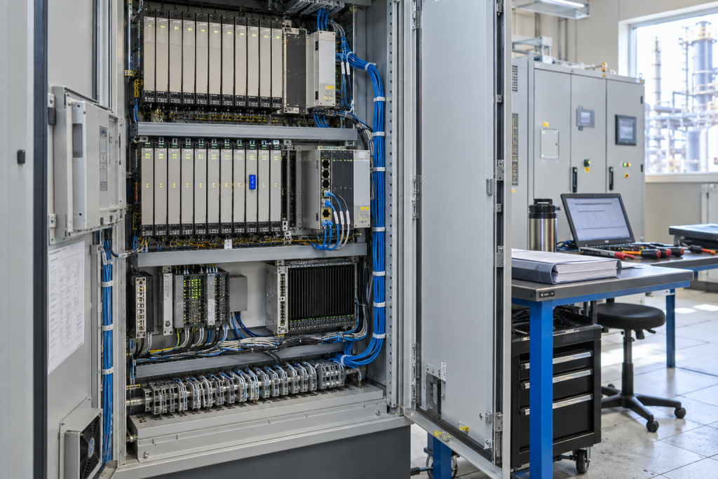
When the fault evidence points to a regulator or excitation board, capture the full type and order code, hardware revision, installed firmware or configuration, supply and sensing ratings, terminal and connector arrangement, redundant-channel role, and cabinet photos. The published ABB UNITROL 1000 excitation system is a relevant catalog reference, not a blanket interchangeability statement. Require the seller to identify the exact offered item and its test condition.
If vibration trips are part of the restart sequence, document that protection path separately rather than folding it into AVR diagnosis. A GE IS200VVIBH1CAB vibration card belongs to a different function and needs its own channel, rack and configuration evidence. Keep separate material requests and acceptance tests so that a turbine protection issue is not mistaken for an excitation fault.
Define the return-to-service hold points
Before energization, have controls, electrical and operations staff agree on setpoint, limiter and protection checks, field flashing requirements if applicable, breaker sequence, trip response, and abort criteria. Check configuration against the approved baseline and verify that temporary grounds, test leads, jumpers and bypasses are accounted for. Assign one person to call each hold point so that several teams do not change settings at once.
During the first build-up, trend terminal voltage, field current, reactive power, limiter activity and alarms. Confirm stable response at the planned operating points and verify the protection chain according to the approved test procedure. Close the event with as-found/as-left settings, serial numbers, test results and any unresolved variance. This makes the next outage a planned engineering task rather than another emergency board order.
Questions Maintenance Teams Ask
Does a no-voltage build-up prove the AVR has failed?
No. Sensing, reference, field circuit, interlocks, supply and protection can all prevent build-up. Isolate those boundaries with approved measurements before selecting a replacement.
Can I use the model number alone to order a UNITROL spare?
No. Confirm the complete type code, revision, configuration, interfaces, sensing and supply ratings, redundancy role, and site acceptance requirements.
Should the excitation board be bench tested?
A documented bench test can add evidence, but it cannot reproduce every installed sensing, field-load, grounding and protection interaction. Record the test limits.
What should be trended during restart?
Use the approved plan to trend generator terminal voltage, field current, reactive output, limiter state, protection alarms and relevant breaker feedback on a common time base.
For an excitation-system inquiry, send NINERMAS the complete regulator and board labels, cabinet and terminal photos, generator voltage class, field arrangement, fault sequence, required condition, and outage window. We can help check the part identity and evidence needed for a responsible sourcing decision.
© 2026 NINERMAS. All rights reserved. Official Website: https://NINERMAS.com Inquiry: sale@NINERMAS.com | WhatsApp/Tel: +86 187 5021 5667
Next Step
Move the research into a cleaner RFQ.
Send the part number, quantity, condition expectation, destination, and timing details so the sourcing team can reply with better availability and lead-time context.