Original Industrial Spare Part
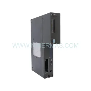
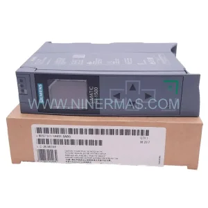
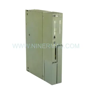
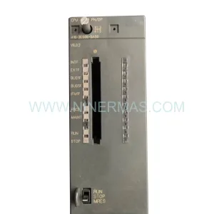
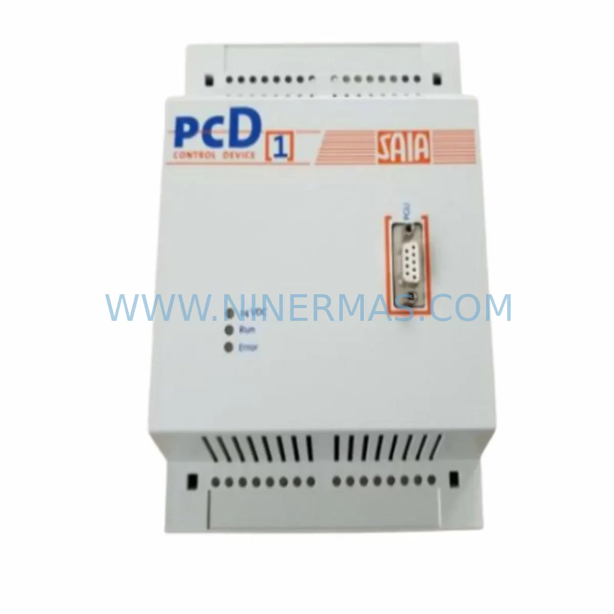
SAIA PCD1.M110 Retrofit-Compatible CPU for Legacy Systems
Verify the part, confirm the platform family, and move straight into quotation with the right commercial details.
RFQ Ready
- SKUPCD1.M110
- CategoryPLC & Industrial Automation Modules
- BrandSAIA
- SupportAvailability, lead time, condition, and shipping coordination
How Buyers Usually Use This Page
- Confirm the exact part number and platform family before sending the quote request.
- Use direct email when quantity, condition, and destination are already defined internally.
- Switch to the broader brand or category archive when you need alternates nearby.
Series Navigation
Move through the most common platform families behind this part.
Product RFQ
Send this part directly for quotation.
Include quantity, required condition, destination country, and target delivery timing. Current reference: SAIA PCD1.M110 Retrofit-Compatible CPU for Legacy Systems with SKU PCD1.M110.
SAIA PCD1.M110 Retrofit-Compatible CPU Module: Seamless Legacy System Modernization
The SAIA PCD1.M110 is a compact CPU module designed for the PCD1 programmable controller series, widely deployed across building automation, industrial process control, and infrastructure management applications. As the PCD1 platform approaches end-of-life and spare parts availability tightens, the PCD1.M110 remains one of the most sought-after retrofit and replacement components for engineers tasked with extending the operational life of existing control systems without committing to a full platform migration.
At NINERMAS, we maintain verified stock of the SAIA PCD1.M110 to support customers managing aging PCD1 installations. Whether you are replacing a failed CPU, building a cold-standby spare inventory, or executing a phased modernization of a legacy control cabinet, the PCD1.M110 provides a reliable, cost-effective path forward. Each unit is pre-shipment tested and covered by our 12-month warranty.
Upgrade Compatibility Table
| Parameter | Details |
|---|---|
| Model | SAIA PCD1.M110 |
| Series | PCD1 |
| Module Type | CPU / Central Processing Unit |
| Backplane Compatibility | PCD1 series base units and expansion racks |
| Communication Interfaces | S-Bus (serial), optional Ethernet via communication module |
| I/O Expansion | Supports PCD1 local I/O modules and remote I/O via S-Bus |
| Programming Environment | SAIA PG5 (compatible with legacy PG3/PG4 project migration) |
| Power Supply Requirement | 24 VDC via PCD1 base unit power module |
| Installation Form Factor | Plug-in module, PCD1 rack-mount |
| Replacement Compatibility | Direct replacement for PCD1.M110 and compatible with PCD1.M120 migration paths |
| Commissioning Notes | Program reload via PG5 required; verify DB and flag assignments post-swap |
| Warranty | 12 months from date of shipment |
Retrofit Planning for Existing Automation Systems
Replacing a SAIA PCD1.M110 in an operational facility requires careful pre-planning to avoid unplanned downtime and configuration loss. Before removing the existing CPU, engineers should back up the full PG5 project — including all data blocks (DBs), flag memory, timer presets, and communication node addresses — using the SAIA PG5 programming software connected via the onboard serial port or a PCD7.F150 programming cable.
The PCD1 platform uses a modular rack architecture. When planning the swap, confirm that the replacement PCD1.M110 is seated correctly in the CPU slot of the PCD1 base unit, and that all adjacent I/O modules — such as PCD1.W300 digital input modules, PCD1.W400 digital output modules, and PCD1.W600 analog input modules — are firmly connected and addressed correctly. Module addressing in the PCD1 system is slot-dependent, so physical slot positions must match the I/O configuration defined in the PG5 project.
If the existing installation includes a PCD7.D457 operator panel or a third-party HMI connected via S-Bus, verify that the node address assigned to the PCD1.M110 in the new unit matches the original configuration. S-Bus node conflicts are a common source of communication failure after CPU replacement and can cause the HMI to lose visibility of process variables immediately after restart.
For installations where the PCD1 communicates upstream to a SCADA system or a supervisory PLC via Modbus RTU or S-Bus over RS-485, the communication parameters — baud rate, parity, stop bits, and node ID — must be re-verified after the CPU swap. These settings are stored in the CPU’s program memory and will be restored when the PG5 project is reloaded, but physical wiring at the terminal block should be inspected for continuity before powering up.
In control cabinets where space is constrained, confirm that the PCD1.M110 module dimensions are compatible with the existing DIN rail or rack mounting arrangement. The PCD1 series uses a compact form factor, but adjacent components such as PCD1.N100 power supply modules, circuit breakers, and cable ducts may limit access during the swap procedure. Plan the physical replacement sequence before beginning work.
Where the legacy system includes PCD1 expansion racks connected via the internal bus, verify that the expansion rack addressing and the number of configured I/O points remain within the PCD1.M110’s supported range. If the original installation was running near the CPU’s memory or I/O capacity limits, this is also an appropriate time to evaluate whether a migration to the PCD2 or PCD3 platform — using modules such as the PCD2.M480 or PCD3.M3340 — would better serve long-term operational requirements.
Downtime Control During System Migration
Minimizing downtime during a PCD1.M110 CPU replacement begins with preparation. Before the maintenance window opens, the full PG5 project should be compiled, verified, and stored on a dedicated engineering laptop with PG5 installed and licensed. A printed copy of the I/O assignment list, S-Bus node table, and communication parameter sheet should be available on-site as a reference independent of any network connection.
During the swap, the sequence should follow a defined procedure: power down the PCD1 base unit, remove the failed CPU module, insert the replacement PCD1.M110, restore power, and immediately download the verified PG5 project before enabling any field outputs. This sequence prevents the CPU from entering an undefined state with uninitialized outputs that could trigger unexpected actuator movement or process upsets.
If the process cannot tolerate a full shutdown, consider whether the affected control loop can be placed in manual mode at the field level — for example, by switching a local control station to manual or isolating the relevant field devices — while the CPU swap is performed. This approach preserves process continuity in adjacent loops while the PCD1.M110 is replaced and recommissioned.
After the PG5 project is downloaded and the CPU enters RUN mode, perform a structured verification: check all digital input status indicators against known field conditions, verify analog input readings against local instrumentation, confirm that all S-Bus communication links are active, and validate HMI screen data against live process values before returning the system to automatic control. Document the replacement date, firmware version of the new module, and any configuration changes made during the procedure for the site maintenance record.
Retrofit Support FAQ
Q1: Is the SAIA PCD1.M110 a direct drop-in replacement for a failed PCD1 CPU?
Yes. The PCD1.M110 is designed as a plug-in replacement for the PCD1 CPU slot. After physical installation, the original PG5 project must be downloaded to the new module using the SAIA PG5 programming software. No hardware modifications to the base unit or I/O modules are required for a like-for-like replacement.
Q2: Does NINERMAS test the PCD1.M110 before shipment?
Yes. All units undergo pre-shipment functional testing to verify basic CPU operation, memory integrity, and communication port functionality. Each unit is shipped with a 12-month warranty covering manufacturing defects and functional failures under normal operating conditions.
Q3: What programming cable is required to connect to the PCD1.M110?
The PCD1.M110 uses a standard SAIA serial programming interface. The PCD7.F150 programming cable is the recommended connection tool for use with SAIA PG5 software. Ensure the correct COM port and baud rate are configured in PG5 before attempting to connect to the module.
Q4: Can NINERMAS supply other PCD1 series components alongside the PCD1.M110?
Yes. We maintain stock of a range of PCD1 series components to support complete retrofit and spare parts programs. Contact our team at sale@ninermas.com to discuss your full bill of materials and lead time requirements.
| Product Series | Legacy |
|---|
Catalog Continuation
More SAIA modules in the catalog.
Use the brand lane to compare nearby part numbers, platform-adjacent modules, and other inquiry-ready listings before sending your final RFQ.
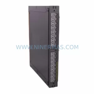
Catalog Continuation
Alternative parts within PLC & Industrial Automation Modules.
Stay inside the same system family when you need substitutes, adjacent modules, or a broader shortlist for procurement review.
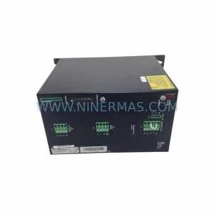
SKU: SCE906A2-002-01 SCE906A200201
Pacific Scientific SCE906A2-002-01 Retrofit Servo Amplifier
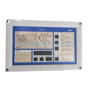
SKU: EPC500 3183062451
Alfa Laval EPC500 3183062451 Service-Ready Spare Part