Original Industrial Spare Part
ROBICON A5E01649325 Retrofit-Compatible Drive for Legacy Systems
Verify the part, confirm the platform family, and move straight into quotation with the right commercial details.
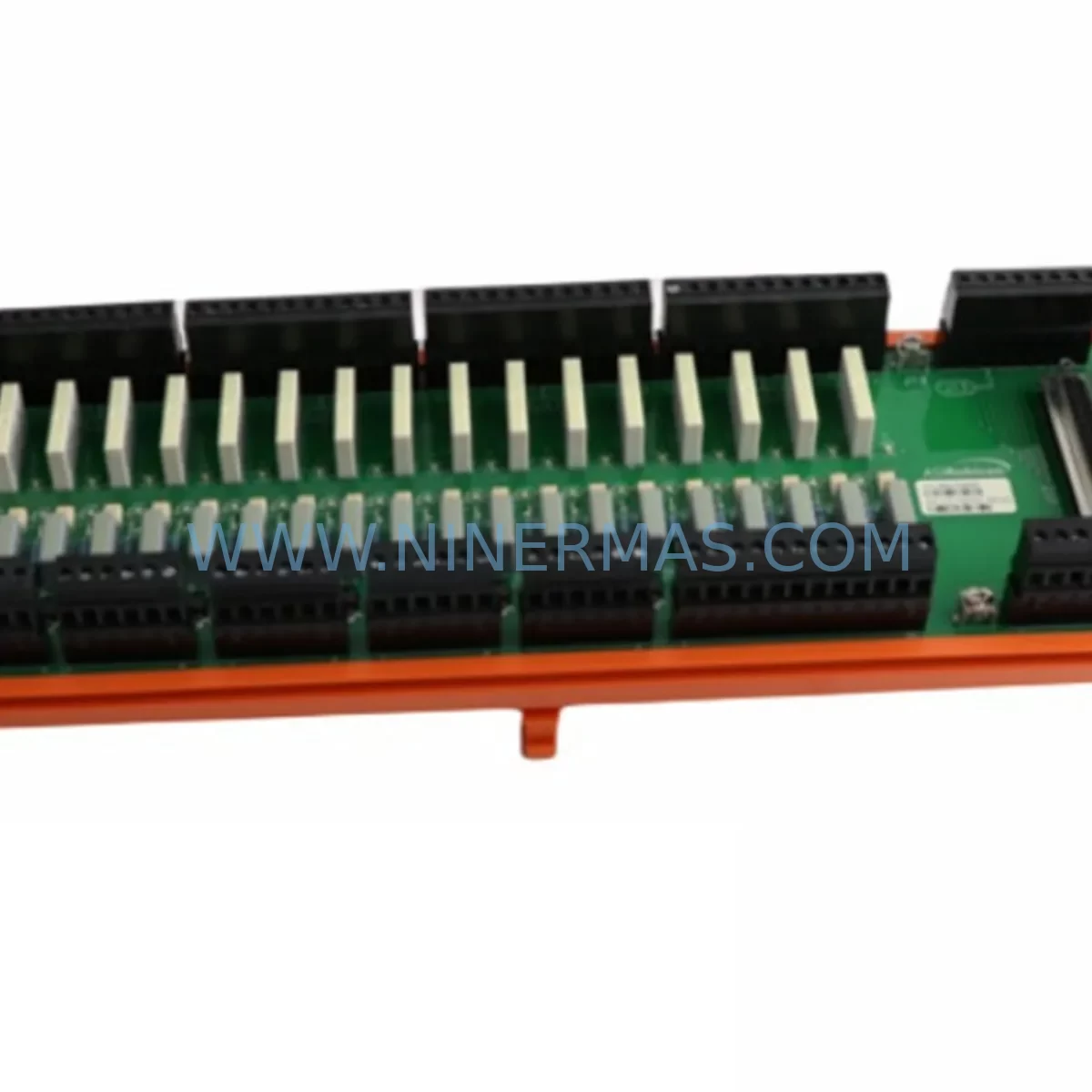
RFQ Ready
- SKUA5E01649325
- CategoryPLC & Industrial Automation Modules
- BrandRobicon
- SupportAvailability, lead time, condition, and shipping coordination
How Buyers Usually Use This Page
- Confirm the exact part number and platform family before sending the quote request.
- Use direct email when quantity, condition, and destination are already defined internally.
- Switch to the broader brand or category archive when you need alternates nearby.
Series Navigation
Move through the most common platform families behind this part.
Product RFQ
Send this part directly for quotation.
Include quantity, required condition, destination country, and target delivery timing. Current reference: ROBICON A5E01649325 Retrofit-Compatible Drive for Legacy Systems with SKU A5E01649325.
ROBICON A5E01649325 Retrofit-Compatible Drive for Legacy Systems
The ROBICON A5E01649325 is a retrofit-compatible variable frequency drive module designed as a direct replacement and upgrade solution for aging Perfect Harmony Drive series installations. As industrial facilities face increasing pressure to extend the operational life of legacy motor control infrastructure, the A5E01649325 provides a reliable, drop-in compatible path to modernize medium-voltage drive systems without requiring full panel redesign or extended production shutdowns. This unit is sourced, pre-tested, and supplied with a 12-month warranty, making it a preferred choice for maintenance engineers and procurement teams managing critical rotating equipment in power generation, oil and gas, water treatment, mining, and heavy process industries.
The Perfect Harmony Drive platform, originally engineered for demanding medium-voltage applications, remains widely deployed across global industrial sites. However, sourcing original spare parts for discontinued or end-of-life variants has become increasingly difficult. The A5E01649325 addresses this gap by offering a verified replacement that maintains electrical compatibility with existing backplane connections, power cell architecture, and control wiring layouts. Engineers undertaking a retrofit project must confirm the existing power cell voltage rating, fiber optic communication links between the cell controller and the main control board, and the physical cell bay dimensions before installation. The A5E01649325 is compatible with the standard 19-inch cell bay format used across multiple Perfect Harmony generations.
When planning a retrofit around the A5E01649325, the broader system context must be carefully evaluated. The Perfect Harmony architecture relies on a distributed power cell topology where each cell contributes to the output voltage waveform. Replacing a single cell module such as the A5E01649325 requires verifying that the cell bypass unit, typically a component like the A5E00285646 bypass module, remains functional and correctly addressed. The cell controller board, often referenced as the A5E00174561 or equivalent generation variant, must be confirmed compatible with the replacement cell firmware version to avoid communication faults on the fiber optic ring. Additionally, the main control unit — such as the A5E01649326 or the A5E00174560 master controller — should be checked for software revision alignment before commissioning the replacement cell.
Terminal wiring adaptation is a critical step during installation. The A5E01649325 uses a standardized DC bus connection and AC output terminal block layout consistent with the Perfect Harmony cell bay standard, but engineers should verify torque specifications and conductor sizing against the existing installation drawings. The input rectifier section and the IGBT output stage within the cell are pre-assembled and factory-tested, reducing field assembly risk. However, the fiber optic cables connecting the cell to the cell controller board must be inspected for bend radius compliance and connector cleanliness before reconnection, as signal degradation on the fiber ring is a common source of cell communication faults post-replacement.
For sites running legacy PROFIBUS DP or Modbus RTU communication protocols to the drive’s main control unit, the A5E01649325 replacement does not require protocol reconfiguration at the cell level, as communication is handled internally via the fiber optic ring. However, if the site is also undertaking a broader migration to PROFINET or EtherNet/IP at the drive system level, this is an appropriate time to evaluate upgrading the communication interface module — such as the A5E00285648 PROFIBUS adapter or its PROFINET successor — in parallel with the cell replacement. Coordinating these changes during a single planned outage minimizes total downtime and reduces the number of future maintenance windows required.
HMI screen updates are another consideration when replacing drive components in a Perfect Harmony system. If the site uses a Siemens OP17, TP177, or equivalent operator panel connected to the drive’s control unit, the HMI project should be reviewed to confirm that any cell-level diagnostic screens or fault code displays remain accurate after the replacement. Cell numbering and addressing within the drive’s internal configuration must match the physical installation sequence to ensure correct fault localization on the HMI. This is particularly important in multi-cell configurations where the drive output voltage is built across six, nine, or more series-connected cells.
Installation space confirmation is essential before ordering. The A5E01649325 cell module fits within the standard Perfect Harmony cell bay envelope, but sites with non-standard enclosure modifications or added cable management trays should measure the available insertion depth and width clearance. The cell extraction and insertion process requires a cell handling tool compatible with the specific bay rail system; this tool is typically retained on-site from the original drive commissioning kit. If the handling tool is unavailable, it should be sourced before scheduling the replacement outage to avoid delays.
Pre-shipment testing is performed on every A5E01649325 unit before dispatch. Each module undergoes DC bus charging verification, IGBT gate drive functional test, and fiber optic transceiver output level measurement. A test report is available upon request. Units are shipped in anti-static packaging with foam cell protection to prevent transit damage to the ceramic capacitors and IGBT modules within the cell assembly. Delivery lead times are confirmed at the time of order, with expedited shipping available for critical breakdown situations.
Upgrade Compatibility Table
| Parameter | Details |
|---|---|
| Replacement SKU | A5E01649325 |
| Brand | ROBICON (Siemens Perfect Harmony) |
| Series | Perfect Harmony Drive |
| Module Type | Medium-Voltage Power Cell Module |
| Cell Bay Format | Standard 19-inch Perfect Harmony cell bay |
| Communication Interface | Fiber optic ring (internal cell-to-controller) |
| Compatible Control Protocols | PROFIBUS DP, Modbus RTU (drive system level) |
| Bypass Module Compatibility | A5E00285646 and equivalent bypass units |
| Cell Controller Compatibility | A5E00174561 and equivalent generation variants |
| Installation Requirement | Cell handling tool, fiber optic inspection, torque verification |
| Pre-Shipment Testing | DC bus charge, IGBT gate drive, fiber optic transceiver output |
| Packaging | Anti-static, foam-protected cell enclosure |
| Warranty | 12 months from date of shipment |
| Origin | Germany (OEM-equivalent specification) |
Retrofit Planning for Existing Automation Systems
A successful retrofit centered on the A5E01649325 requires a structured approach to system mapping before any physical work begins. The first step is to document the existing cell configuration: how many cells are installed per phase, the current cell addressing scheme stored in the main control unit, and the firmware version running on each cell controller board. In a typical Perfect Harmony 6 kV or 11 kV drive, each output phase is built from three or more series-connected cells, meaning a single cell failure can trigger a full drive trip if the bypass function is not active. Confirming that the A5E00285646 bypass module assigned to the failed cell position is operational before the replacement cell arrives prevents a situation where the bypass itself requires attention during the same outage window.
The main control unit — whether a first-generation A5E00174560 master controller or a later-revision A5E01649326 — stores the drive’s parameter set, including motor nameplate data, speed reference scaling, torque limits, and protection thresholds. Before removing the faulty cell, a full parameter backup should be performed using the drive’s built-in parameter upload function or via the STARTER commissioning tool connected through the RS232 or USB service port on the control board. This backup protects against accidental parameter loss during the cell swap and provides a restore point if the replacement cell triggers a configuration mismatch fault on first power-up.
Signal isolation between the drive’s control section and the power cell section is maintained through the fiber optic ring. Each cell in the ring must be present and communicating for the drive to complete its self-test sequence. When the A5E01649325 replacement cell is installed, the fiber optic connectors must be seated fully and the ring continuity verified using the drive’s diagnostic menu before closing the cell bay doors and applying power. If the site also has a signal isolator — such as a Phoenix Contact or Weidmüller DIN-rail isolator — on the 4–20 mA speed reference input to the drive’s analog input board, this should be checked for calibration drift as part of the broader maintenance window. Similarly, the 24 VDC auxiliary power supply feeding the cell controller boards, often a Siemens SITOP PSU100S or equivalent, should be load-tested to confirm it can support the full cell ring without voltage sag.
For sites where the Perfect Harmony drive is integrated into a DCS or SCADA system via a PROFIBUS DP network, the drive’s GSD file and station address assignment should be verified against the network configuration after the cell replacement. If the main control board was also replaced or reset during the maintenance window, the PROFIBUS station address may revert to a default value, causing the DCS to lose communication with the drive. This check takes less than five minutes but prevents a potentially lengthy fault-finding exercise during drive recommissioning. If the site is planning a future migration from PROFIBUS to PROFINET, the A5E00285648 communication adapter replacement can be scheduled as a follow-on activity once the A5E01649325 cell replacement has been validated in service.
Downtime Control During System Migration
Minimizing downtime during a Perfect Harmony cell replacement requires preparation that begins well before the scheduled outage. The A5E01649325 should be on-site and inspected before the maintenance window opens. The replacement cell’s fiber optic connectors, DC bus terminals, and cell bay rail engagement points should be visually checked against the installation drawing for the specific drive model. Having the cell handling tool, torque wrench, fiber optic cleaning kit, and a laptop with the STARTER software pre-loaded on-site eliminates the most common causes of outage extension.
The recommended sequence for a cell replacement outage is: safe isolation and lockout of the drive’s MV input breaker, discharge verification of the DC bus using a calibrated high-voltage probe, physical removal of the faulty cell using the handling tool, installation of the A5E01649325 replacement cell with fiber optic reconnection and terminal torquing, fiber ring continuity check via the drive diagnostic menu, parameter restore from backup if required, and controlled power-up with monitoring of the drive’s fault log for the first five minutes of operation. This sequence, when followed by a trained technician, typically completes within two to four hours for a single-cell replacement, keeping the production impact to a minimum.
Protecting the original program logic stored in the site’s PLC — whether a Siemens S7-300, S7-400, or a third-party controller managing the drive’s start/stop and speed reference signals — is equally important. The cell replacement does not affect the PLC program directly, but if the drive’s control unit was also reset or replaced, the drive’s internal logic functions, such as catch-on-the-fly restart, automatic bypass activation, and speed ramp profiles, must be re-verified against the site’s process requirements before returning the drive to automatic control. A brief manual test run at reduced speed, with the process isolated, confirms that the replacement cell is performing correctly before full load is applied.
Retrofit Support FAQ
Q: Is the A5E01649325 a direct drop-in replacement for the original Perfect Harmony cell in my drive?
A: Yes, the A5E01649325 is designed as a retrofit-compatible replacement for the Perfect Harmony power cell position it was originally specified for. Confirm the cell bay voltage rating and physical dimensions match your installation before ordering. Our technical team can assist with compatibility verification based on your drive’s nameplate data.
Q: What pre-shipment testing is performed on the A5E01649325?
A: Every unit undergoes DC bus charging verification, IGBT gate drive functional testing, and fiber optic transceiver output level measurement before dispatch. A test report is available upon request. Units are shipped in anti-static, foam-protected packaging to prevent transit damage.
Q: How do I verify fiber optic ring continuity after installing the replacement cell?
A: After seating the A5E01649325 and reconnecting the fiber optic cables, access the drive’s diagnostic menu on the main control unit. The cell communication status screen will display each cell’s ring position and communication state. All cells must show a healthy status before the drive will complete its self-test and allow a start command. Clean fiber connectors with an appropriate optical cleaning tool if any cell shows a communication fault.
Q: What warranty coverage is provided, and what does it include?
A: The A5E01649325 is supplied with a 12-month warranty from the date of shipment. The warranty covers manufacturing defects and component failures under normal operating conditions. It does not cover damage resulting from incorrect installation, overvoltage events, or operation outside the specified environmental ratings. Warranty claims are supported directly by NINERMAS with replacement or repair as appropriate.
| Product Series | Legacy |
|---|
Catalog Continuation
More Robicon modules in the catalog.
Use the brand lane to compare nearby part numbers, platform-adjacent modules, and other inquiry-ready listings before sending your final RFQ.
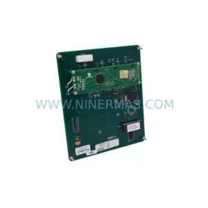
SKU: A1A460A68.23M/460A68.10
ROBICON A1A460A68.23M Service-Ready Spare Part for Industrial Maintenance
Catalog Continuation
Alternative parts within PLC & Industrial Automation Modules.
Stay inside the same system family when you need substitutes, adjacent modules, or a broader shortlist for procurement review.
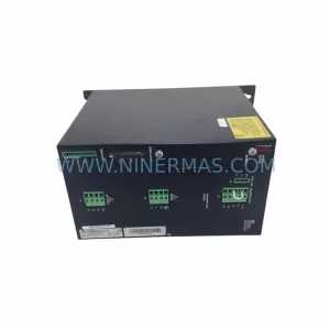
SKU: SCE906A2-002-01 SCE906A200201
Pacific Scientific SCE906A2-002-01 Retrofit Servo Amplifier
SKU: EPC500 3183062451
Alfa Laval EPC500 3183062451 Service-Ready Spare Part