Original Industrial Spare Part
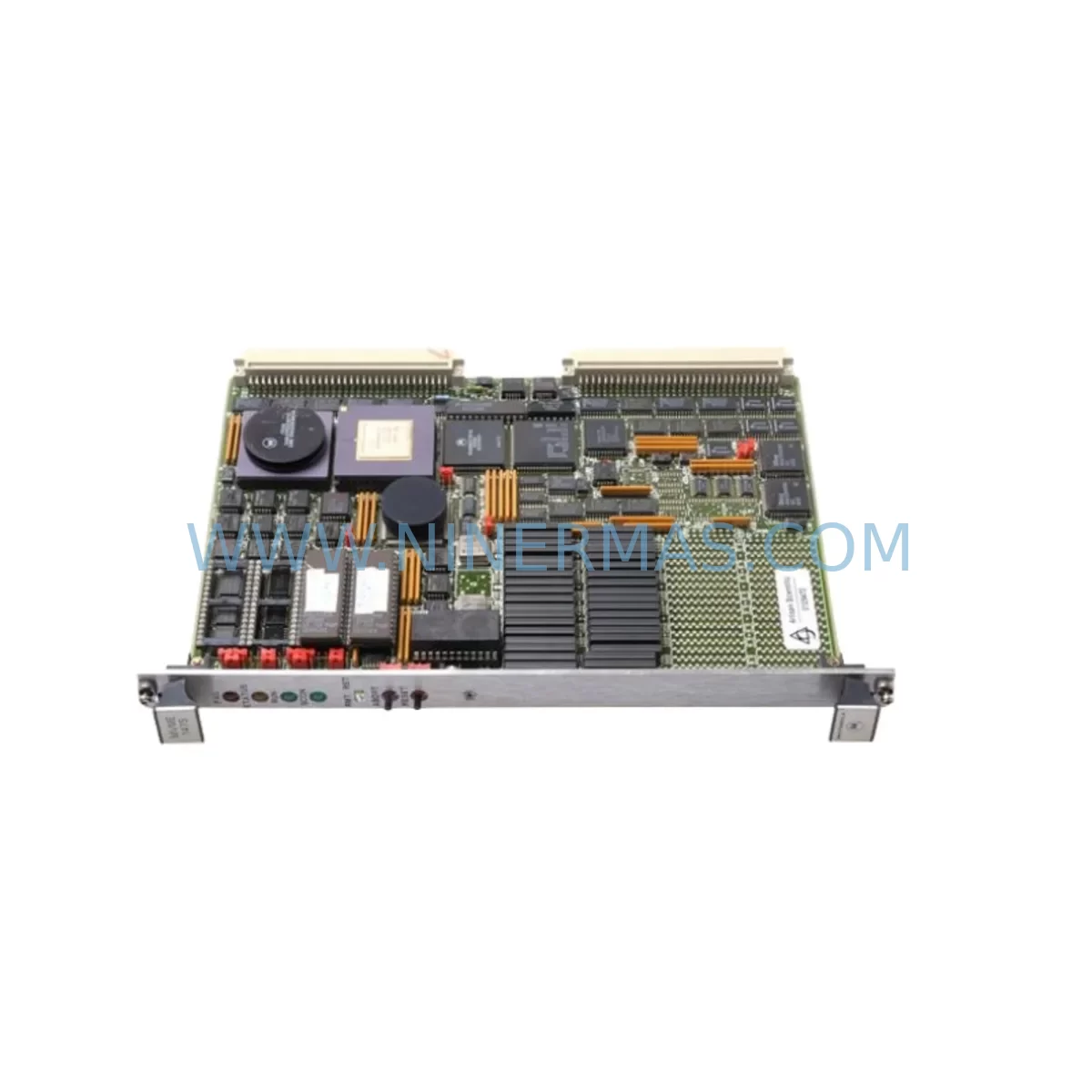
Motorola 147S-1 Service-Ready Spare Part for Industrial Maintenance
Verify the part, confirm the platform family, and move straight into quotation with the right commercial details.
RFQ Ready
- SKU147S-1
- CategoryPLC & Industrial Automation Modules
- BrandMotorola
- SupportAvailability, lead time, condition, and shipping coordination
How Buyers Usually Use This Page
- Confirm the exact part number and platform family before sending the quote request.
- Use direct email when quantity, condition, and destination are already defined internally.
- Switch to the broader brand or category archive when you need alternates nearby.
Series Navigation
Move through the most common platform families behind this part.
Product RFQ
Send this part directly for quotation.
Include quantity, required condition, destination country, and target delivery timing. Current reference: Motorola 147S-1 Service-Ready Spare Part for Industrial Maintenance with SKU 147S-1.
Motorola 147S-1 Service-Ready Spare Part for Industrial Maintenance
The Motorola 147S-1 is a high-performance VMEbus CPU board from the MVME 147 series, designed for demanding industrial automation and process control environments. Built on the Motorola 68030 processor architecture, this board delivers reliable real-time computing performance for legacy VME-based control systems that remain in active service across manufacturing plants, power utilities, and process industries worldwide. When a 147S-1 fails or degrades, the impact is immediate: production lines halt, control loops open, and maintenance teams face intense pressure to restore operation with minimal downtime. Sourcing a verified, service-ready replacement is the fastest path back to normal operation.
At NINERMAS, every 147S-1 unit is individually inspected, functionally tested, and shipped with a 12-month warranty. Our procurement network spans original manufacturer channels and certified industrial surplus sources, ensuring that each board meets the electrical and firmware specifications required for direct drop-in replacement in your existing VME chassis.
Spare Maintenance Table
| Parameter | Specification |
|---|---|
| Part Number | 147S-1 |
| Series | Motorola MVME 147 |
| Processor | Motorola MC68030 @ 25 MHz |
| Bus Standard | VMEbus (IEEE 1014) |
| On-Board RAM | 4 MB DRAM (expandable) |
| Serial Ports | 4 × RS-232C (Z85C30 SCC) |
| Ethernet | 10BASE-T / AUI (AMD LANCE) |
| SCSI Interface | NCR 53C710 SCSI-2 |
| Operating Voltage | +5 VDC, ±12 VDC via VME backplane |
| Operating Temperature | 0°C to +55°C |
| Form Factor | 6U VME Single Board Computer |
| Compatibility | VME 6U chassis, MVME 147 series variants |
| Firmware | MVME147Bug ROM Monitor |
| Warranty | 12 Months — NINERMAS Certified |
Maintenance Planning for Continuous Operation
Replacing a 147S-1 CPU board is rarely an isolated task. Maintenance engineers working on VMEbus systems understand that the CPU board is the nerve center of the control rack, and its failure often coincides with — or is caused by — degradation in adjacent components. A thorough site inspection during replacement significantly reduces the risk of repeat failures and unplanned downtime.
Begin by inspecting the VME backplane itself. Backplane connector pins on aging VME chassis can develop oxidation or micro-fractures that cause intermittent bus errors, which are frequently misdiagnosed as CPU board failures. While the 147S-1 is removed, clean and inspect all J1/J2 connector rows. If the chassis is a Motorola MVME 945 or similar 6U VME enclosure, check the backplane power distribution rails for voltage sag under load.
The power supply feeding the VME rack is the next critical checkpoint. VMEbus systems require tightly regulated +5 VDC and ±12 VDC rails. An aging industrial power supply — such as a Motorola MVME 901 or equivalent third-party VME power module — may deliver marginal voltage that causes the CPU board to reset or fail to boot. Measure rail voltages under load before installing the replacement 147S-1.
Serial communication integrity is essential for systems using the 147S-1’s four RS-232C ports for HMI connectivity or PLC communication. Inspect the serial interface cables connecting the board to operator panels, terminal servers, or SCADA workstations. Damaged or improperly shielded cables introduce noise that can corrupt serial data streams. If the system uses a Motorola MVME 712 transition module or similar I/O transition card for serial breakout, verify that the transition module’s connectors and termination resistors are in good condition.
For systems with SCSI-attached storage — common in older DCS and SCADA architectures using the 147S-1 as a data acquisition node — inspect the SCSI cable, terminator, and connected drives or solid-state SCSI emulators. A failing SCSI terminator is a frequent cause of boot failures that appear to implicate the CPU board. Consider replacing the SCSI terminator as a precautionary measure during any 147S-1 swap.
Ethernet connectivity should also be validated. The 147S-1’s onboard AMD LANCE Ethernet controller connects via AUI or 10BASE-T. Inspect the AUI transceiver or media converter if present, and verify that the network switch port is operating at the correct speed and duplex settings. In plant environments, Ethernet transceivers and media converters are often overlooked during spare parts planning but are common single points of failure.
Finally, review the VME slot configuration. If the 147S-1 is installed alongside I/O boards such as Motorola MVME 162 or MVME 172 single-board computers, MVME 2700 series digital I/O modules, or third-party analog input boards, confirm that the VME slot addressing and interrupt priority assignments are correctly configured on the replacement board. Jumper and DIP switch settings on the 147S-1 control base address, IRQ level, and DRAM configuration — these must match the original board’s settings to ensure seamless system restart.
Site Replacement Workflow
Step 1 — Pre-Replacement Documentation: Before powering down, photograph or record the existing board’s jumper and DIP switch configuration. Note the VME slot position, cable routing, and any labels on connected cables. Capture the current firmware revision from the MVME147Bug ROM monitor if accessible.
Step 2 — Controlled Shutdown: Execute a graceful system shutdown through the operating software (VxWorks, OS-9, or UNIX variant) to prevent file system corruption on SCSI-attached storage. If the system does not support graceful shutdown, power down the VME chassis using the main power switch rather than pulling the board under power.
Step 3 — Board Extraction: Use the VME board ejector levers to disengage the 147S-1 from the backplane. Avoid flexing the board during extraction. Place the removed board in an anti-static bag immediately.
Step 4 — Replacement Board Preparation: Configure the replacement 147S-1’s jumpers and DIP switches to match the documented settings from Step 1. Verify DRAM size configuration, base address selection, and serial port mode settings. If the replacement board carries a different firmware revision, consult the MVME147Bug release notes for compatibility considerations.
Step 5 — Installation and Power-Up: Insert the replacement board into the correct VME slot, ensuring full engagement of both J1 and J2 connectors. Reconnect all cables. Power up the chassis and observe the ROM monitor boot sequence. Confirm that the board passes its self-test and that all peripherals (SCSI, Ethernet, serial ports) are recognized.
Step 6 — System Validation: Restore the application software from backup media or network boot. Verify communication with all connected I/O modules, HMI panels, and network nodes. Run a functional test of all control loops before returning the system to production.
Spare Parts Support FAQ
Q: Is the 147S-1 still available as a new or refurbished spare?
A: The Motorola MVME 147S-1 has been discontinued by the original manufacturer. NINERMAS sources verified original units through certified industrial channels. Each unit undergoes functional testing prior to shipment. Stock availability is subject to market supply — contact us to confirm current inventory and lead time.
Q: How do I verify compatibility between a replacement 147S-1 and my existing VME system?
A: Compatibility is determined by VME slot size (6U), backplane connector standard (J1/J2), processor architecture (68030), and firmware revision. Provide your chassis model, operating system, and application software version when inquiring, and our technical team will confirm compatibility before shipment.
Q: What testing is performed before the 147S-1 is shipped?
A: Every unit is powered up in a compatible VME test chassis, subjected to ROM monitor self-test, SCSI and Ethernet interface verification, and serial port loopback testing. Units that fail any test are quarantined and not offered for sale. A test report summary is available upon request.
Q: What does the 12-month warranty cover?
A: The NINERMAS 12-month warranty covers functional failure under normal operating conditions. It does not cover damage resulting from incorrect installation, overvoltage, or physical mishandling. In the event of a warranty claim, we provide a replacement unit or full refund after technical review. Long-term supply agreements with extended warranty terms are available for volume procurement customers.
| Product Series | Other series |
|---|
Catalog Continuation
More Motorola modules in the catalog.
Use the brand lane to compare nearby part numbers, platform-adjacent modules, and other inquiry-ready listings before sending your final RFQ.
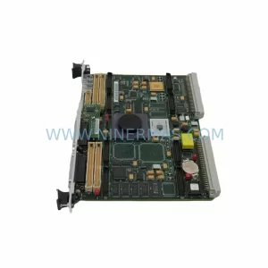
Catalog Continuation
Alternative parts within PLC & Industrial Automation Modules.
Stay inside the same system family when you need substitutes, adjacent modules, or a broader shortlist for procurement review.
SKU: PVD300 17-307113-00 2301407-B SM2315D-BRK 02-306362-00
Novellus 307113-00 Service-Ready Spare Part for Maintenance
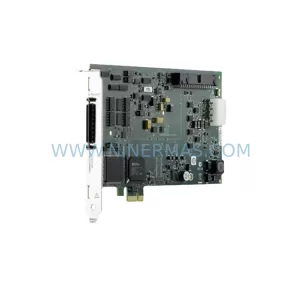
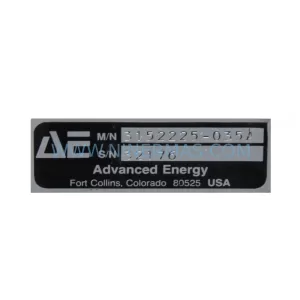
SKU: 3152225-035A MDX-10K AP1415S 2PW MVE4 MVE4 P 23020202-B
Advanced Energy 3152225-035A Retrofit-Compatible RF Generator
SKU: PQM0A100EXXYST0
SANYO PQM0A100EXXYST0 Retrofit-Compatible Power Supply