Original Industrial Spare Part
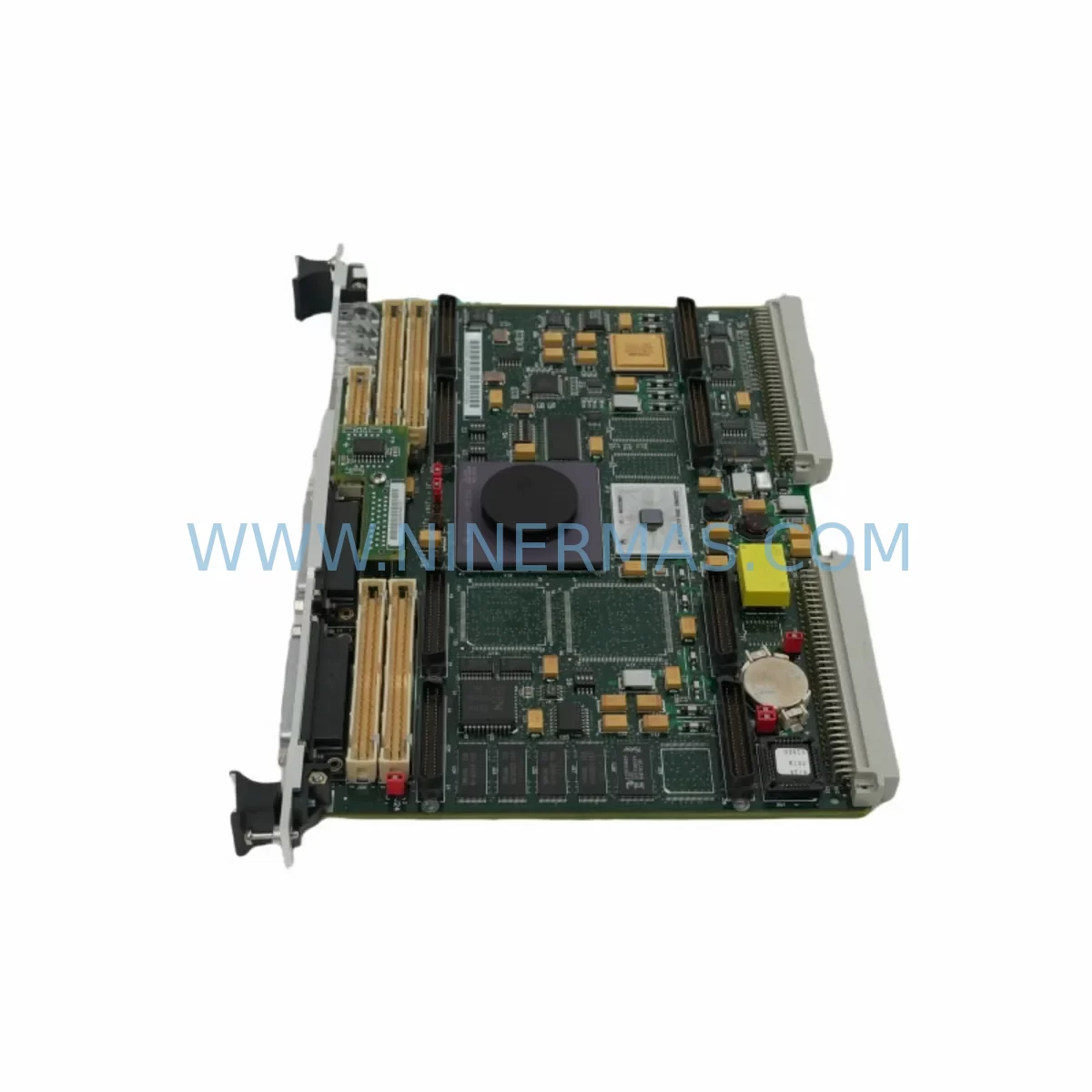
Motorola MVME162P-244L Retrofit-Compatible CPU for Legacy Systems
Verify the part, confirm the platform family, and move straight into quotation with the right commercial details.
RFQ Ready
- SKUMVME162P-244L
- CategoryPLC & Industrial Automation Modules
- BrandMotorola
- SupportAvailability, lead time, condition, and shipping coordination
How Buyers Usually Use This Page
- Confirm the exact part number and platform family before sending the quote request.
- Use direct email when quantity, condition, and destination are already defined internally.
- Switch to the broader brand or category archive when you need alternates nearby.
Series Navigation
Move through the most common platform families behind this part.
Product RFQ
Send this part directly for quotation.
Include quantity, required condition, destination country, and target delivery timing. Current reference: Motorola MVME162P-244L Retrofit-Compatible CPU for Legacy Systems with SKU MVME162P-244L.
Motorola MVME162P-244L Retrofit-Compatible CPU for Legacy Systems
The Motorola MVME162P-244L is a high-performance VMEbus embedded controller designed for seamless integration into legacy automation environments. As a direct retrofit-compatible replacement within the MVME162 series, this module addresses the growing demand for reliable spare parts, discontinued component substitution, and control system modernization across manufacturing, energy, transportation, and process industries. Whether you are recovering a failed system, extending the service life of an aging control cabinet, or executing a phased migration to a modern platform, the MVME162P-244L provides the compatibility, stability, and supply assurance your operation requires.
Built around the Motorola 68040 processor architecture, this module slots directly into standard VME64 and VMEbus backplanes, maintaining full mechanical and electrical compatibility with existing rack infrastructure. Engineers managing legacy Motorola MVME systems will find that the MVME162P-244L preserves the original I/O mapping, interrupt vectors, and memory addressing schemes that existing application software depends upon — dramatically reducing the risk of program logic errors during replacement.
Upgrade Compatibility Table
| Parameter | MVME162P-244L Specification | Retrofit Notes |
|---|---|---|
| Processor | Motorola 68040 @ 25 MHz | Pin-compatible with MVME162-2xx variants |
| Bus Interface | VMEbus (IEEE 1014) / VME64 | Compatible with standard 6U VME backplanes |
| Memory | 4 MB DRAM, 512 KB Flash | Verify application memory map before swap |
| Serial Ports | 4 × RS-232/RS-422 | Match terminal wiring to existing DB9/DB25 pinout |
| Ethernet | 10BASE-T (optional) | Confirm IP address and subnet settings post-swap |
| Installation Form Factor | 6U VME single-slot | Confirm slot clearance in existing chassis |
| Operating Voltage | +5 VDC (±5%), +12 VDC | Verify backplane PSU capacity before installation |
| Communication Protocols | RS-232, RS-422, Ethernet TCP/IP | Re-validate protocol settings in application firmware |
| Replacement Recommendation | Direct drop-in for MVME162-2xx series | Cross-reference jumper settings with original module |
| Commissioning Focus | Boot sequence, I/O scan, comms link test | Use MVME162 debugger (167Bug/162Bug) for validation |
| Warranty | 12 Months | Covered from date of shipment; includes DOA replacement |
Retrofit Planning for Existing Automation Systems
Successful integration of the MVME162P-244L into an existing control system begins well before the physical swap. Retrofit engineers should start by auditing the current rack configuration, documenting every module installed in the VMEbus chassis — including power supply modules such as the MVME712M transition module, any installed MVME332XT serial I/O boards, and MVME712-12 P2 adapter cards that route rear-panel I/O signals. Understanding the full backplane population ensures that the replacement CPU does not conflict with existing geographic addressing or bus arbitration settings.
Terminal wiring is a critical checkpoint. On systems where the MVME162P-244L interfaces with field devices through rear-panel P2 connectors, engineers must verify that the existing cable harness matches the new module’s P2 pinout. In many legacy installations, custom transition boards or breakout panels were fabricated to adapt standard VMEbus P2 signals to plant-floor terminal blocks — these adapters must be inspected and, if necessary, re-pinned to match the MVME162P-244L’s signal assignments.
Power budget verification is equally important. The MVME162P-244L draws current from the +5 VDC and +12 VDC backplane rails. Before installation, calculate the total current demand of all modules in the chassis — including any MVME177 or MVME187 companion processors, MVME374 memory expansion boards, or MVME2300-series communication modules that may share the same power supply. If the existing power supply is operating near its rated capacity, a replacement or supplemental PSU should be sourced before the retrofit proceeds.
For systems that include HMI interfaces — particularly older operator panels running proprietary display software linked to the MVME162 via RS-232 or RS-422 serial links — the communication parameters (baud rate, parity, stop bits, flow control) must be documented and replicated exactly on the MVME162P-244L. In installations where the HMI communicates over Ethernet using a TCP/IP socket connection, the replacement module’s IP address, subnet mask, and gateway must be pre-configured using the onboard 162Bug firmware debugger before the module is inserted into the live rack.
Module address configuration deserves particular attention in multi-CPU VMEbus systems. If the MVME162P-244L is being installed alongside other processors — for example, a MVME167 or MVME177 acting as a secondary controller — the VMEbus system controller jumper (J1) and bus request level settings must be set to avoid address conflicts. Incorrect geographic addressing is one of the most common causes of post-retrofit boot failures and can be resolved quickly by consulting the MVME162P hardware reference manual and comparing jumper positions against the original module’s configuration photograph taken during disassembly.
Program compatibility should be validated in a staging environment whenever possible. If the application firmware was compiled for the 68040 instruction set and stored in the original module’s Flash memory, a binary image should be extracted and transferred to the MVME162P-244L using a compatible programming cable or network boot server. For systems running VxWorks, LynxOS, or a custom RTOS, confirm that the board support package (BSP) version matches the MVME162P-244L hardware revision to avoid peripheral initialization failures at boot time.
Downtime Control During System Migration
Minimizing unplanned downtime is the primary concern for any control system retrofit. When replacing the MVME162P-244L in a production environment, the recommended approach is to pre-configure and bench-test the replacement module fully before scheduling the maintenance window. This includes loading the application firmware, setting all jumpers and DIP switches to match the original module, verifying serial port communication with a test terminal, and confirming Ethernet connectivity if applicable.
During the maintenance window itself, follow a structured swap procedure: power down the VMEbus chassis in the correct sequence (application software shutdown first, then OS halt, then power removal), extract the failed module, insert the pre-configured MVME162P-244L, restore power, and monitor the boot sequence through the front-panel serial debug port. The 162Bug firmware will report any hardware initialization errors during POST, allowing the technician to identify and resolve issues before the application software is launched.
To protect original program logic, always maintain a verified backup of the application binary, configuration files, and any non-volatile RAM (NVRAM) parameter sets stored on the original module. NVRAM data — which often contains calibration constants, PID tuning parameters, recipe data, and communication node addresses — is not automatically transferred to a replacement module and must be manually restored using the 162Bug memory load commands or a dedicated NVRAM programming utility.
Field control continuity can be maintained during brief swap operations by placing upstream controllers or safety PLCs into a hold or manual mode, ensuring that field outputs remain in a safe, defined state while the VMEbus CPU is offline. For processes where even a few minutes of open-loop operation is unacceptable, a hot-standby redundancy configuration using a second VMEbus chassis with a pre-loaded MVME162P-244L can be implemented to achieve near-zero switchover time.
All units supplied by NINERMAS are subject to pre-shipment functional testing, including power-on self-test verification, serial port loopback testing, and memory read/write validation. Each MVME162P-244L is shipped with a 12-month warranty covering manufacturing defects and functional failures, with DOA replacement processed within 48 hours of confirmed fault report.
Retrofit Support FAQ
Q1: Is the MVME162P-244L a direct drop-in replacement for other MVME162 variants such as the MVME162-262 or MVME162-232?
A: The MVME162P-244L is mechanically and bus-compatible with the broader MVME162 product family. However, processor speed, memory configuration, and optional feature sets vary between sub-models. Before substitution, compare the original module’s order number suffix against the MVME162P-244L specification sheet to confirm that memory capacity, serial port count, and optional Ethernet or SCSI features match your application requirements. In most retrofit scenarios, the MVME162P-244L is a functional equivalent with minor firmware adjustments.
Q2: What wiring and terminal changes are required when installing the MVME162P-244L into an existing cabinet?
A: In the majority of direct replacements, no wiring changes are required at the P1 connector level. P2 rear-panel wiring should be verified against the MVME162P-244L P2 signal map, as custom transition boards in legacy installations may have been wired to a different sub-variant’s pinout. Serial port DB9 connectors on the front panel are standard RS-232/RS-422 and are compatible with existing cabling in most installations.
Q3: How is compatibility verified before shipment, and what does the 12-month warranty cover?
A: Every MVME162P-244L unit dispatched by NINERMAS undergoes a pre-shipment test protocol that includes power-on self-test (POST) completion, memory integrity check, and serial port functional verification. The 12-month warranty covers all manufacturing defects and functional failures under normal operating conditions. It does not cover damage resulting from incorrect installation, overvoltage, or physical impact. Warranty claims are processed within 5 business days, with advance replacement available for critical production applications.
Q4: Can NINERMAS assist with sourcing complementary modules needed for a complete system retrofit?
A: Yes. NINERMAS maintains inventory of a broad range of VMEbus and legacy industrial control components, including power supply modules, serial I/O boards, memory expansion cards, communication modules, and transition hardware. If your retrofit requires additional components beyond the MVME162P-244L, contact our technical sales team with your full BOM and we will provide availability and lead time information for each line item.
| Product Series | Legacy |
|---|
Catalog Continuation
More Motorola modules in the catalog.
Use the brand lane to compare nearby part numbers, platform-adjacent modules, and other inquiry-ready listings before sending your final RFQ.
Catalog Continuation
Alternative parts within PLC & Industrial Automation Modules.
Stay inside the same system family when you need substitutes, adjacent modules, or a broader shortlist for procurement review.
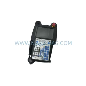
SKU: A05B-2518-C200
FANUC A05B-2518-C200 Retrofit Teach Pendant for Legacy Systems
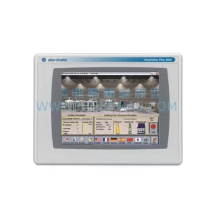
SKU: 2711PC-T10C4D8
Allen-Bradley 2711PC-T10C4D8 Retrofit-Compatible HMI Terminal