Original Industrial Spare Part
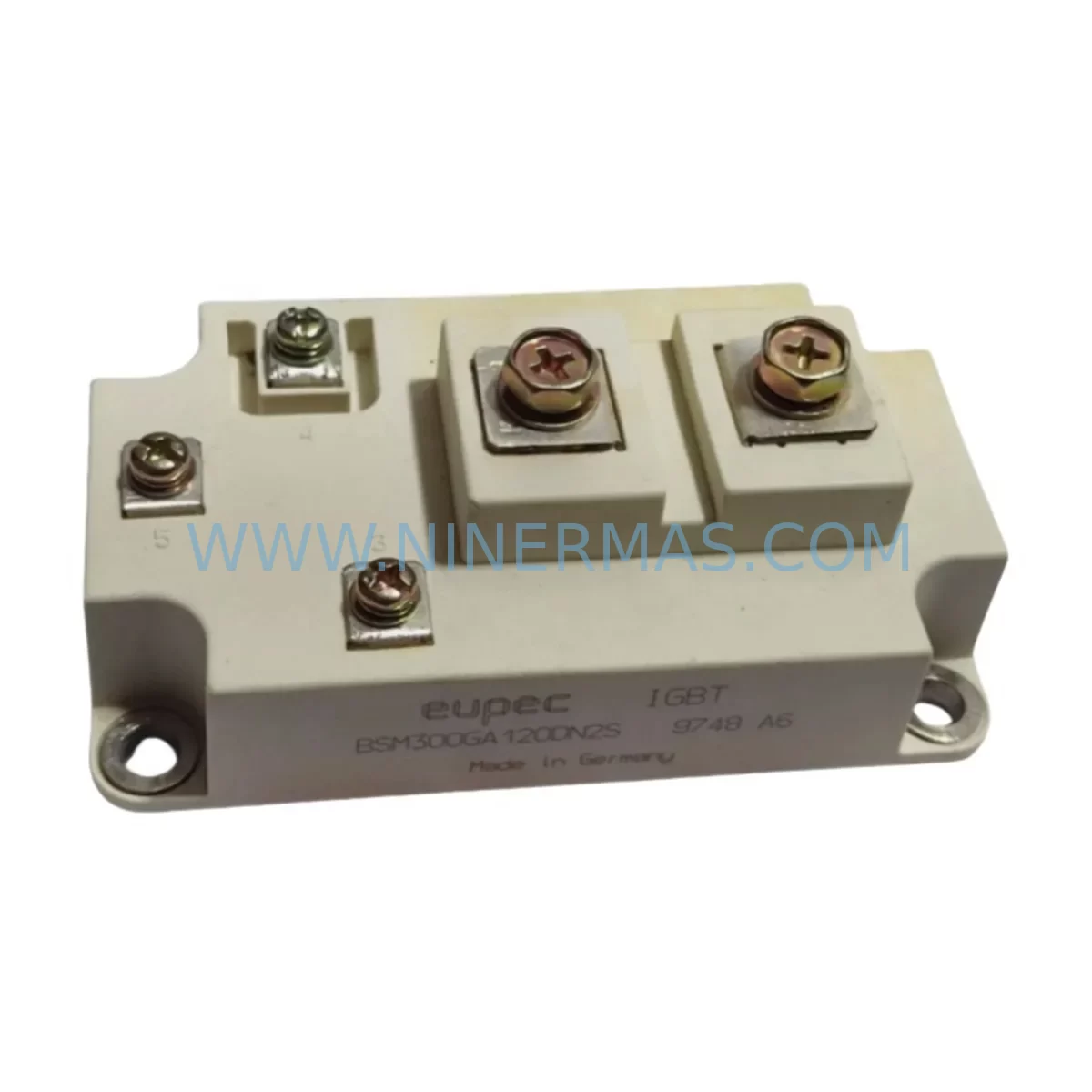
EUPEC BSM300GA120DN2S Retrofit-Compatible IGBT Module
Verify the part, confirm the platform family, and move straight into quotation with the right commercial details.
RFQ Ready
- SKUBSM300GA120DN2S
- CategoryPLC & Industrial Automation Modules
- BrandEUPEC
- SupportAvailability, lead time, condition, and shipping coordination
How Buyers Usually Use This Page
- Confirm the exact part number and platform family before sending the quote request.
- Use direct email when quantity, condition, and destination are already defined internally.
- Switch to the broader brand or category archive when you need alternates nearby.
Series Navigation
Move through the most common platform families behind this part.
Product RFQ
Send this part directly for quotation.
Include quantity, required condition, destination country, and target delivery timing. Current reference: EUPEC BSM300GA120DN2S Retrofit-Compatible IGBT Module with SKU BSM300GA120DN2S.
EUPEC BSM300GA120DN2S Retrofit-Compatible IGBT Module: Legacy System Compatibility & Smooth Upgrade Path
The EUPEC BSM300GA120DN2S is a high-performance 300A / 1200V IGBT power module engineered for demanding industrial drive and inverter applications. As a retrofit-compatible replacement within the GA120DN2 series, this module is purpose-built to support legacy automation system upgrades, discontinued spare parts substitution, and control cabinet modernization — without requiring full system redesign. NINERMAS maintains verified in-stock inventory of the BSM300GA120DN2S to support planned maintenance windows, emergency breakdowns, and long-term spare parts procurement programs.
Industrial facilities operating aging variable frequency drives (VFDs), medium-voltage inverters, traction converters, and servo drive platforms frequently encounter the challenge of sourcing discontinued IGBT modules. The BSM300GA120DN2S addresses this directly: its standardized 62mm power module footprint, dual-switch half-bridge topology, and isolated copper baseplate allow it to slot into existing heatsink assemblies with minimal mechanical rework. Engineers responsible for retrofit planning can rely on this module’s consistent gate threshold voltage (VGE(th)) and collector-emitter saturation voltage (VCE(sat)) characteristics to maintain original drive tuning parameters during commissioning.
Upgrade Compatibility Table
| Parameter | BSM300GA120DN2S Specification | Retrofit / Replacement Notes |
|---|---|---|
| Collector Current (IC) | 300A @ 25°C | Verify drive’s rated output current does not exceed module rating under derating conditions |
| Collector-Emitter Voltage (VCES) | 1200V | Confirm DC bus voltage headroom; 1200V class suitable for 690V AC drive systems |
| Module Package | 62mm Standard Power Module | Direct mechanical fit for existing 62mm heatsink assemblies; no baseplate modification required |
| Gate Drive Voltage | ±15V recommended | Compatible with standard IGBT gate driver boards (e.g., CONCEPT, Semikron SKYPER series); verify dead-time settings |
| Isolation Voltage | 4000Vrms | Meets IEC 60664 creepage/clearance requirements for industrial control cabinet installation |
| Thermal Interface | Copper baseplate | Apply fresh thermal compound (e.g., Wacker P12 or equivalent) during reinstallation; torque to OEM specification |
| Communication Compatibility | N/A (power stage) | Upper-level control (PROFIBUS, PROFINET, CANopen, Modbus RTU) unaffected by module swap |
| Replacement Series | GA120DN2 / DN2S family | Cross-reference with BSM300GA120DLC, BSM300GA120DT, BSM200GA120DN2S for adjacent ratings |
| Installation Space | Standard 62mm module envelope | Confirm clearance for DC bus busbars and gate driver PCB standoffs before installation |
| Warranty | 12-Month Warranty — All BSM300GA120DN2S units shipped by NINERMAS carry a 12-month warranty covering manufacturing defects under normal operating conditions | |
Retrofit Planning for Existing Automation Systems
Successful integration of the BSM300GA120DN2S into a legacy drive system requires a structured pre-installation assessment. Before scheduling a maintenance window, the retrofit engineering team should audit the existing control cabinet for the following critical parameters.
Power Supply Capacity: Confirm that the DC link capacitor bank and rectifier bridge assembly can sustain the 300A peak current demand of the replacement module. In older drive platforms — particularly those originally designed around lower-rated IGBT stacks — the DC bus power supply unit (PSU) may require a parallel capacitor upgrade to maintain voltage stability during transient load events. This is especially relevant in multi-axis servo systems where the shared DC bus feeds multiple inverter stages simultaneously.
Terminal Wiring and Busbar Connections: The BSM300GA120DN2S uses M6 screw terminals for collector and emitter connections. Inspect existing copper busbars for oxidation, micro-cracking, or deformation from previous thermal cycling. Replace any degraded busbars before reinstalling the module. Torque all power terminals to the manufacturer’s specified value (typically 6–8 Nm for M6 connections) to prevent contact resistance buildup and localized heating.
Backplane and Rack Interface: In modular drive architectures — such as those using Siemens SIMOVERT or ABB ACS series drive racks — the IGBT power module interfaces with a dedicated gate driver board mounted on the drive’s internal backplane. Verify that the gate driver board’s output voltage levels, blanking time, and short-circuit protection thresholds are compatible with the BSM300GA120DN2S gate characteristics. If the existing gate driver board (for example, a CONCEPT 2SD315A or equivalent) shows signs of aging or parameter drift, replace it concurrently to avoid nuisance tripping after the module swap.
Module Address and I/O Configuration: For drive systems with intelligent power module (IPM) feedback loops or temperature monitoring via NTC thermistor outputs, confirm that the replacement module’s NTC resistance-temperature curve matches the original. The BSM300GA120DN2S incorporates an integrated NTC thermistor; verify that the drive’s thermal protection threshold is calibrated to this module’s specific R-T characteristic to prevent false over-temperature faults. Similarly, if the drive uses an I/O expansion module or a dedicated condition monitoring card to log module junction temperature, update the scaling parameters in the drive’s configuration software accordingly.
Program Compatibility and HMI Screens: The BSM300GA120DN2S swap is a power-stage replacement and does not alter the drive’s control firmware or PLC program logic. However, if the original drive system was commissioned with module-specific fault codes mapped to an HMI panel (for example, a Siemens TP700 Comfort or Allen-Bradley PanelView), review the alarm configuration to ensure that any module-specific diagnostic codes are correctly mapped to the replacement unit’s fault output signals. Update HMI screen descriptions and alarm text where necessary to reflect the new module part number for future maintenance traceability.
Communication Link Integrity: The BSM300GA120DN2S operates as a pure power switching device and does not participate in the drive’s fieldbus communication stack. PROFIBUS DP, PROFINET IO, CANopen, or Modbus RTU communication between the drive controller and the plant PLC remains unaffected by the module replacement. However, if the drive’s control board — which may include a CP1616 communication processor or equivalent — was disturbed during the module removal process, perform a full communication link test after reassembly before returning the drive to automatic mode.
Related Components Commonly Required During BSM300GA120DN2S Retrofit: In practice, a BSM300GA120DN2S replacement is rarely performed in isolation. Field engineers typically identify and address adjacent component wear during the same maintenance window. Commonly replaced or inspected items include the DC link capacitor bank, gate resistor network on the driver PCB, NTC thermistor signal conditioning module, AC input fuses and DC bus fuse, snubber capacitors mounted across the module terminals, the heatsink fan assembly and its associated 24VDC fan power supply, the IGBT gate driver board (such as a CONCEPT 2SD315A-17 or Semikron SKYPER 32R), and the fiber optic PWM signal cable connecting the control board to the gate driver. In multi-module parallel configurations, the current sharing inductor and busbar symmetry should also be verified. Addressing these components concurrently minimizes the risk of a repeat failure and reduces total lifecycle maintenance cost.
Downtime Control During System Migration
Minimizing production downtime during an IGBT module replacement is a primary concern for plant maintenance managers. A well-executed BSM300GA120DN2S swap can be completed within a planned 4–8 hour maintenance window when the following protocol is observed.
Pre-Shutdown Preparation: Before initiating the shutdown sequence, capture a full backup of the drive’s parameter set using the drive manufacturer’s commissioning software (e.g., Siemens STARTER, ABB Drive Composer, or Rockwell Studio 5000 Logix Designer). Store the parameter backup on a dedicated maintenance laptop and a secondary USB drive. This ensures that if the drive’s non-volatile memory is inadvertently cleared during the power cycling process, the original tuning data — including speed loop gains, current regulator parameters, encoder feedback scaling, and fieldbus node address — can be restored without re-commissioning from scratch.
Safe Isolation and Discharge: After initiating the drive’s controlled stop sequence, allow the DC bus capacitors to fully discharge before opening the control cabinet. Verify residual DC bus voltage with a calibrated high-voltage multimeter. Do not rely solely on the drive’s internal discharge resistor; in older drives, the bleed resistor may have degraded. Confirm voltage below 50V DC before touching any internal components.
Module Removal and Inspection: Document the existing wiring layout with photographs before disconnecting any terminals. Label all gate driver signal cables, NTC thermistor leads, and power busbars. Remove the faulty BSM300GA120DN2S by releasing the module mounting screws in a cross-pattern sequence to avoid baseplate stress. Inspect the heatsink surface for thermal compound residue, corrosion, or mechanical damage. Clean the heatsink contact surface with isopropyl alcohol before applying fresh thermal interface material.
Post-Installation Verification: After installing the replacement BSM300GA120DN2S and reconnecting all terminals, perform an insulation resistance test (megger test) between the power terminals and the heatsink ground before energizing. Power up the drive in a no-load test mode and verify that the gate driver outputs are producing correct PWM switching waveforms on all six gate channels (for a three-phase inverter bridge). Confirm that the drive’s current feedback signals are balanced across all phases before connecting the motor load. Run the drive at reduced speed and load for a minimum of 30 minutes to verify thermal stability before returning to full production speed.
Protecting Original Program Logic: The PLC program controlling the drive’s start/stop, speed reference, and fault reset sequences does not require modification. Confirm that the drive’s ready signal and fault relay outputs are functioning correctly before releasing the system to automatic operation. Update the maintenance log with the replacement date, new module serial number, and commissioning engineer’s name to support future warranty claims and lifecycle tracking.
Retrofit Support FAQ
Q1: Is the BSM300GA120DN2S a direct drop-in replacement for the original GA120DN2 series module?
A: Yes. The BSM300GA120DN2S is dimensionally and electrically compatible with the GA120DN2 series footprint. The 62mm standard package, M6 power terminals, and gate pin layout are consistent with the original specification. Minor differences in VCE(sat) and switching time characteristics are within the tolerance range of standard IGBT gate driver designs. No mechanical modification to the heatsink or busbar assembly is required in the majority of retrofit applications. Always verify against the original drive’s IGBT module datasheet before installation.
Q2: What commissioning steps are required after installing the BSM300GA120DN2S?
A: After mechanical installation and terminal reconnection, perform an insulation resistance test, verify gate driver output waveforms, and run a no-load power-up test. Confirm NTC thermistor readings are within the expected range at ambient temperature. Restore the drive parameter backup and run a reduced-load test cycle for a minimum of 30 minutes before returning to full production. No firmware changes are required for a like-for-like module replacement.
Q3: Does NINERMAS provide pre-shipment testing for the BSM300GA120DN2S?
A: Yes. All BSM300GA120DN2S units supplied by NINERMAS undergo pre-shipment functional verification including VCE(sat) measurement, gate threshold voltage check, and insulation resistance test. Units are shipped in anti-static packaging with individual test records. A 12-month warranty is provided from the date of shipment, covering manufacturing defects under normal operating conditions.
Q4: What is the typical lead time and inventory availability for the BSM300GA120DN2S?
A: NINERMAS maintains dedicated buffer stock of the BSM300GA120DN2S to support emergency breakdown and planned maintenance requirements. Standard in-stock orders are dispatched within 1–3 business days. For long-term spare parts programs requiring multi-unit commitments across 12–36 month procurement horizons, NINERMAS offers priority allocation agreements to guarantee supply continuity for critical production lines. Contact our sales team at sale@ninermas.com or +0086 187 5021 5667 to discuss your specific inventory requirements.
| Product Series | Other series |
|---|
Catalog Continuation
More EUPEC modules in the catalog.
Use the brand lane to compare nearby part numbers, platform-adjacent modules, and other inquiry-ready listings before sending your final RFQ.
Catalog Continuation
Alternative parts within PLC & Industrial Automation Modules.
Stay inside the same system family when you need substitutes, adjacent modules, or a broader shortlist for procurement review.
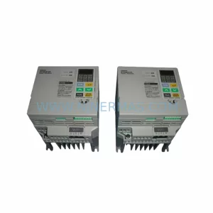
SKU: 3G3EV-AB007M-E
OMRON 3G3EV-AB007M-E Retrofit-Compatible VFD for Legacy Systems
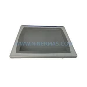
SKU: 2711P-RDT15C SER B
Allen-Bradley 2711P-RDT15C SER B Industrial Spare Part