Original Industrial Spare Part
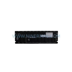
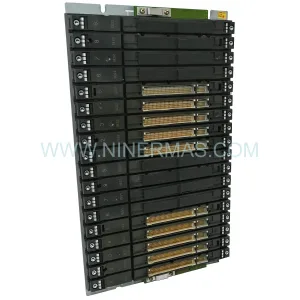
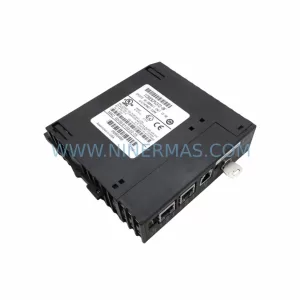
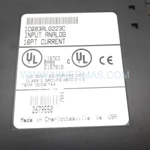
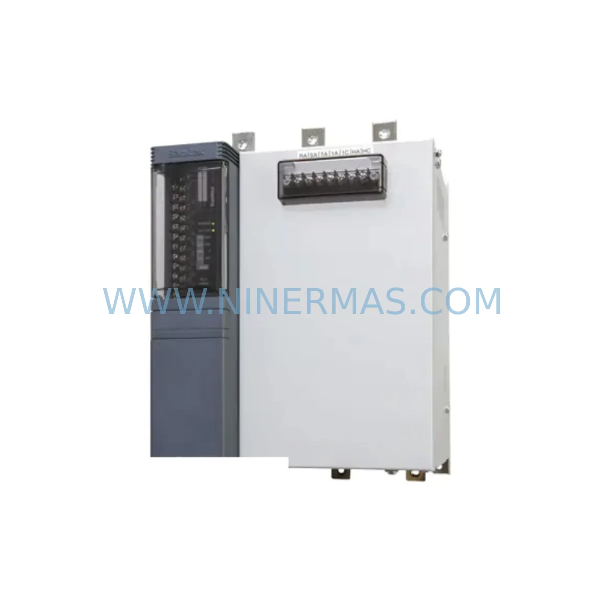
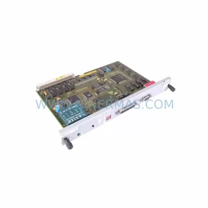
CNC 510.R171-C Retrofit-Compatible I/O Rack for Legacy Systems
Verify the part, confirm the platform family, and move straight into quotation with the right commercial details.
RFQ Ready
- SKU510 RACK 4A 32+32 I/O+BL 510.R171-C
- CategoryPLC & Industrial Automation Modules
- BrandCNC
- SupportAvailability, lead time, condition, and shipping coordination
How Buyers Usually Use This Page
- Confirm the exact part number and platform family before sending the quote request.
- Use direct email when quantity, condition, and destination are already defined internally.
- Switch to the broader brand or category archive when you need alternates nearby.
Series Navigation
Move through the most common platform families behind this part.
Product RFQ
Send this part directly for quotation.
Include quantity, required condition, destination country, and target delivery timing. Current reference: CNC 510.R171-C Retrofit-Compatible I/O Rack for Legacy Systems with SKU 510 RACK 4A 32+32 I/O+BL 510.R171-C.
CNC 510.R171-C Retrofit-Compatible I/O Rack for Legacy Systems
The CNC 510.R171-C is a 510 Series rack module designed for 4A backplane power distribution with 32-input and 32-output I/O expansion capability, plus an integrated backplane (BL) interface. Originally deployed across legacy CNC-controlled manufacturing lines, this rack remains a critical spare for facilities operating aging discrete control architectures where full system replacement is cost-prohibitive or operationally disruptive. NINERMAS maintains verified stock of the 510.R171-C to support planned retrofit programs, emergency spare procurement, and lifecycle extension strategies for existing automation infrastructure.
In legacy CNC 510 Series control cabinets, the rack serves as the physical and electrical backbone connecting I/O modules, power supplies, and the central processor. The 510.R171-C supports up to 32 digital inputs and 32 digital outputs through its integrated backplane bus, making it directly compatible with standard 510 Series I/O modules such as the CNC 510.DI32 digital input module and the CNC 510.DO32 digital output module. When planning a retrofit or spare replacement, engineers must verify that the replacement rack matches the original slot count, backplane bus revision, and power rail configuration to avoid signal integrity issues or module addressing conflicts.
Power supply compatibility is a primary concern during rack replacement. The 510.R171-C operates on a 4A backplane rail, and the field power supply — typically a CNC 510.PS24 or equivalent 24VDC regulated supply — must be confirmed to deliver stable current within the rack’s rated envelope before installation. Undersized or aging power supplies can cause intermittent module faults or prevent the rack from initializing correctly after a cold swap. It is strongly recommended to measure actual current draw across all installed I/O modules before selecting a replacement rack to ensure the 4A rating is not exceeded under full I/O load.
Terminal wiring and field cable routing must be carefully documented before removing the original rack. Each I/O module slot in the 510.R171-C corresponds to a specific terminal block assignment in the original wiring diagram. Technicians should photograph or export the existing terminal layout, verify wire labeling against the original panel drawing, and confirm that field cables are long enough to reach the replacement rack’s terminal positions — particularly if the new rack is installed in a slightly different physical location within the control cabinet. Incorrect terminal reassignment is one of the most common causes of post-retrofit I/O faults.
Module addressing and program compatibility require attention when swapping racks in a live CNC environment. The 510 Series uses slot-based I/O addressing, meaning each physical slot in the rack maps to a fixed address range in the PLC program. If the replacement rack maintains the same slot count and physical layout as the original 510.R171-C, no program changes should be required. However, if the retrofit involves migrating to a newer rack format or a different slot density, the control program — typically managed through a CNC 510 Programming Terminal or compatible offline programming software — must be updated to reflect the new address map before the system is returned to automatic mode.
HMI screen validation is a frequently overlooked step in rack retrofit projects. Operator panels connected to the CNC 510 Series controller, such as legacy CNC OP10 or OP15 operator panels, display I/O status and alarm states that are directly linked to the rack’s I/O module addresses. After replacing the 510.R171-C, all HMI screens should be cycled through their diagnostic views to confirm that input and output status indicators respond correctly to field signals. Any discrepancy between the HMI display and actual field conditions should be investigated before resuming production.
Communication link integrity must also be verified after rack installation. In CNC 510 Series architectures, the rack backplane communicates with the central controller via a proprietary backplane bus. If the system also includes remote I/O nodes connected via PROFIBUS-DP or a similar fieldbus, the rack replacement should not affect remote node communication — but the fieldbus master should be checked for any address conflicts or timeout errors that may have been introduced during the power-down and restart sequence. A CNC 510.CP343 or equivalent communications processor, if installed in the rack, should be re-initialized and its configuration verified against the original network topology.
Installation space confirmation is essential before ordering a replacement rack. The 510.R171-C occupies a defined DIN rail or panel-mount footprint within the control cabinet. Technicians should measure the available mounting depth, width, and cable clearance before the replacement unit arrives on site. In cabinets where space is constrained, the presence of adjacent components such as a CNC 510 signal isolator or terminal marshalling blocks may limit access to the rack’s module slots during installation. Pre-planning the cable management and module insertion sequence can significantly reduce installation time and minimize the risk of damage to adjacent wiring.
All 510.R171-C units supplied by NINERMAS undergo pre-shipment functional testing to verify backplane bus continuity, power rail integrity, and slot connector condition. Each unit is shipped with a test report and is covered by a 12-month warranty from the date of delivery. NINERMAS maintains ongoing inventory of the 510.R171-C and related 510 Series components to support both emergency spare orders and planned retrofit procurement programs with confirmed lead times.
Upgrade Compatibility Table
| Parameter | CNC 510.R171-C Specification | Retrofit / Replacement Notes |
|---|---|---|
| Series | CNC 510 | Direct replacement within 510 Series rack family |
| Backplane Power | 4A rated | Verify total I/O module current draw does not exceed 4A |
| I/O Capacity | 32 DI + 32 DO | Slot-for-slot compatible with 510 Series DI/DO modules |
| Backplane Interface | Integrated BL bus | Must match original backplane bus revision; verify with CNC documentation |
| Communication | Proprietary CNC 510 backplane bus | Compatible with PROFIBUS-DP remote I/O extensions if CP module is installed |
| Mounting | DIN rail / panel mount | Confirm cabinet depth and cable clearance before installation |
| Commissioning | Slot-based I/O addressing | No program changes required if slot count and layout are preserved |
| Warranty | 12-Month | Covered from date of delivery; includes pre-shipment test report |
Retrofit Planning for Existing Automation Systems
A successful 510.R171-C retrofit begins with a thorough audit of the existing control cabinet. Before ordering the replacement rack, document the current slot population — recording which 510 Series modules occupy each slot, including any CNC 510.AI8 analog input modules, CNC 510.AO4 analog output modules, or CNC 510.CP343 communications processors that may be installed alongside the standard digital I/O modules. This slot map becomes the reference for reinstalling modules in the correct positions after the rack swap.
Power sequencing during the retrofit is critical. The field power supply feeding the 510.R171-C should be isolated before any modules are removed. If the control cabinet includes a CNC 510.PS24 24VDC power supply module or an external regulated supply, confirm that the supply is fully de-energized and that residual voltage on the backplane rail has discharged before handling the rack or its connectors. Use a calibrated multimeter to verify zero voltage on the backplane power terminals before proceeding.
For facilities running mixed-generation control architectures — for example, a CNC 510 Series rack controlling legacy machine axes while a newer SINUMERIK 840D sl or equivalent CNC controller manages newer machining centers — the 510.R171-C retrofit can be planned independently without affecting the newer controller’s operation. This modular approach allows maintenance teams to address aging rack infrastructure on a machine-by-machine basis, reducing the scope and risk of each individual retrofit event.
Signal isolators installed between the 510.R171-C’s I/O terminals and field devices — such as proximity sensors, solenoid valves, or servo drive enable signals — should be inspected and tested during the rack replacement. Aging isolators can introduce signal delays or threshold drift that may not be apparent during normal operation but can cause intermittent faults after a rack swap. Replacing worn isolators during the same maintenance window as the rack retrofit minimizes future unplanned downtime.
Programming cable connectivity should be confirmed before closing the cabinet. If the CNC 510 Series controller requires a dedicated CNC programming cable or RS-232/RS-485 interface for online monitoring and parameter backup, verify that the cable connection to the new rack’s processor interface is secure and that the programming terminal can establish communication before the cabinet door is closed and the system is returned to service.
Downtime Control During System Migration
Minimizing downtime during a 510.R171-C rack replacement requires advance preparation and a structured execution sequence. The most effective approach is to complete all pre-work — including slot mapping, terminal photography, program backup, and spare parts staging — during a scheduled maintenance window before the actual rack swap begins. This preparation phase typically takes two to four hours and can be completed while the machine is still in production, provided that the control cabinet can be safely accessed without interrupting the machine’s operating cycle.
Program logic protection is a non-negotiable step. Before powering down the CNC 510 Series controller, create a full backup of the PLC program, including all data blocks, function blocks, and system parameters, using the connected programming terminal or offline backup tool. Store the backup on at least two independent media — for example, a USB drive and a network share — to ensure that the program can be restored quickly if the new rack requires a cold initialization sequence that clears the processor’s memory.
During the physical rack swap, work systematically from one end of the rack to the other, removing and reinstalling modules one at a time in their documented slot positions. Avoid removing all modules simultaneously, as this increases the risk of incorrect reinstallation and extends the time the system is offline. If the replacement 510.R171-C is pre-populated with modules before installation, the total rack swap time can be reduced to under 30 minutes for an experienced technician.
After power-up, perform a structured commissioning check: verify that the processor initializes without fault codes, confirm that all I/O module status LEDs indicate normal operation, cycle each digital input and output through a test sequence using the programming terminal’s force function, and validate HMI screen responses before releasing the machine to automatic mode. Document the commissioning results and retain the pre-shipment test report supplied with the 510.R171-C as part of the machine’s maintenance record.
Retrofit Support FAQ
Q1: Is the CNC 510.R171-C a direct drop-in replacement for other 510 Series racks?
The 510.R171-C is designed for direct replacement within the CNC 510 Series rack family, provided the replacement unit matches the original slot count, backplane bus revision, and power rail rating. Confirm the exact rack variant installed in your system against the CNC 510 Series hardware manual before ordering. NINERMAS can assist with cross-reference verification based on your existing rack’s nameplate data.
Q2: What pre-shipment testing does NINERMAS perform on the 510.R171-C?
Each 510.R171-C unit undergoes functional testing of backplane bus continuity, power rail integrity, and slot connector condition before shipment. A test report is included with every unit. All units are covered by a 12-month warranty from the date of delivery, with support available through sale@ninermas.com.
Q3: Do I need to modify my PLC program after replacing the rack?
If the replacement 510.R171-C maintains the same slot count and physical layout as the original rack, no program changes are required. The CNC 510 Series uses slot-based I/O addressing, so address assignments remain valid as long as module positions are preserved. If the retrofit involves a different slot density or rack format, the program must be updated to reflect the new address map before returning the system to automatic mode.
Q4: Can NINERMAS supply the 510.R171-C for urgent or emergency orders?
Yes. NINERMAS maintains ongoing inventory of the CNC 510.R171-C and related 510 Series components to support both emergency spare procurement and planned retrofit programs. Contact our team at sale@ninermas.com or +0086 187 5021 5667 to confirm current stock availability and lead time for your specific requirement.
| Product Series | Legacy |
|---|
Catalog Continuation
Alternative parts within PLC & Industrial Automation Modules.
Stay inside the same system family when you need substitutes, adjacent modules, or a broader shortlist for procurement review.
SKU: MMC-SD-12.0-460-D
KOLLMORGEN MMC-SD-12.0-460-D Retrofit-Compatible Servo Drive
SKU: BM-DP12 1070075887-202
Bosch BM-DP12 1070075887-202 Retrofit-Compatible PROFIBUS DP Module