Original Industrial Spare Part
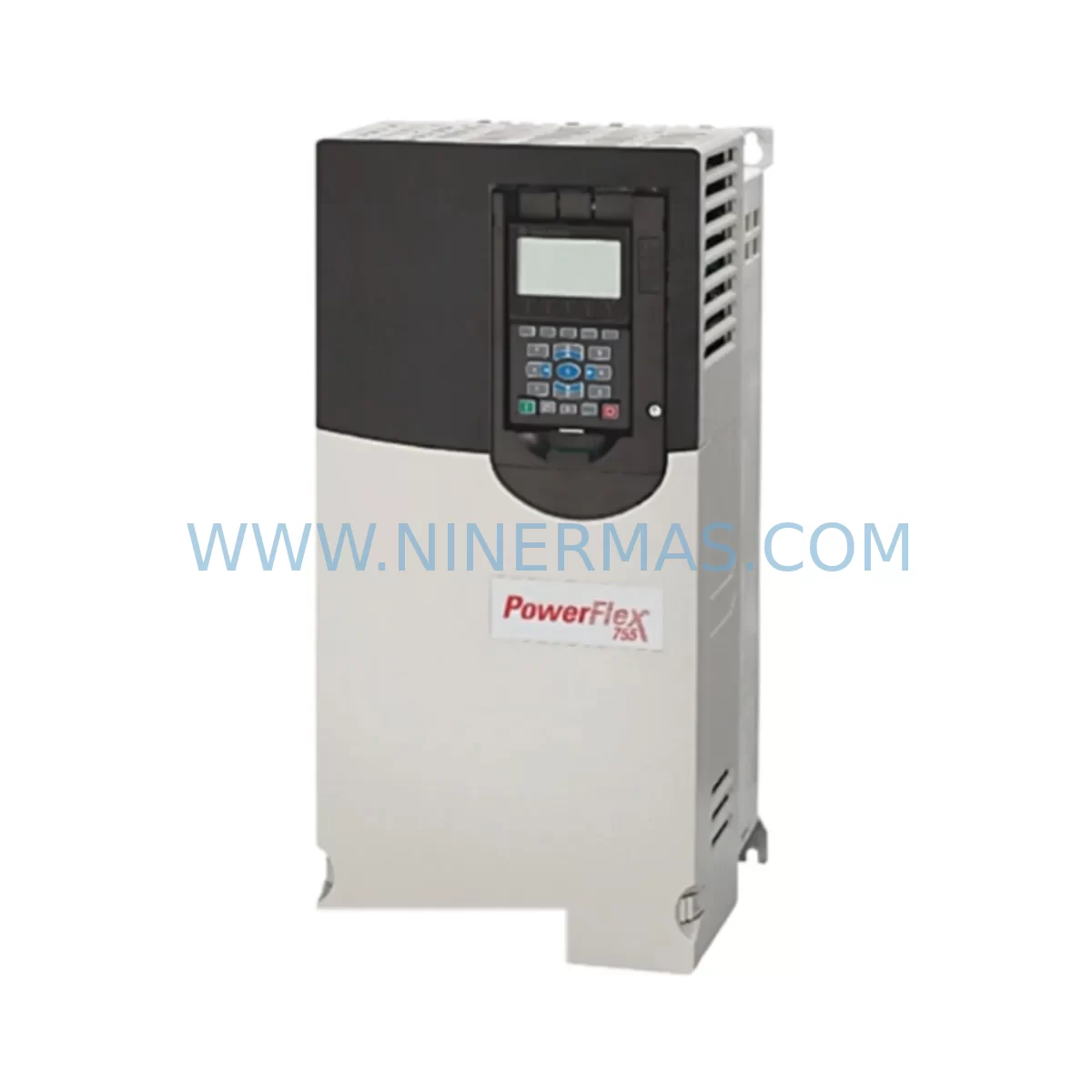
Allen-Bradley 20G14NC104JA0NNNNN Retrofit AC Drive
Verify the part, confirm the platform family, and move straight into quotation with the right commercial details.
RFQ Ready
- SKU20G14NC104JA0NNNNN
- CategoryPLC & Industrial Automation Modules
- BrandAllen-Bradley
- SupportAvailability, lead time, condition, and shipping coordination
How Buyers Usually Use This Page
- Confirm the exact part number and platform family before sending the quote request.
- Use direct email when quantity, condition, and destination are already defined internally.
- Switch to the broader brand or category archive when you need alternates nearby.
Series Navigation
Move through the most common platform families behind this part.
Product RFQ
Send this part directly for quotation.
Include quantity, required condition, destination country, and target delivery timing. Current reference: Allen-Bradley 20G14NC104JA0NNNNN Retrofit AC Drive with SKU 20G14NC104JA0NNNNN.
Allen-Bradley 20G14NC104JA0NNNNN Retrofit-Compatible AC Drive: Legacy System Compatibility & Smooth Upgrade
The Allen-Bradley 20G14NC104JA0NNNNN is a high-performance AC variable frequency drive from the PowerFlex 755 series, engineered for demanding industrial automation environments. As legacy control systems age and original equipment manufacturers discontinue support for older drive platforms, the 20G14NC104JA0NNNNN has become a critical retrofit and replacement solution for engineers managing aging production lines, control cabinets, and multi-axis motion systems. Whether you are replacing a failed unit on an active production floor or planning a phased modernization of your automation infrastructure, this drive offers the compatibility, reliability, and technical depth required for a successful migration.
The PowerFlex 755 platform is widely recognized for its flexibility across a broad range of industrial applications, including conveyors, compressors, pumps, fans, hoists, and precision positioning systems. The 20G14NC104JA0NNNNN variant is rated for 104A output current at 400V AC input, making it suitable for medium-power motor control applications where the original drive may have been a PowerFlex 700, PowerFlex 40, or an earlier generation Bulletin 1336 PLUS II unit. When planning a retrofit, engineers must carefully verify the input voltage range, output current rating, and frame size against the existing installation to ensure a direct or near-direct replacement without requiring panel modifications.
Upgrade Compatibility Table
| Parameter | Details / Recommendation |
|---|---|
| SKU / Part Number | 20G14NC104JA0NNNNN |
| Series | Allen-Bradley PowerFlex 755 |
| Input Voltage | 380–480V AC, 3-Phase |
| Output Current | 104A (Normal Duty) |
| Frame Size | Frame 5 — verify panel cutout and mounting rail dimensions before installation |
| Communication Compatibility | EtherNet/IP, DeviceNet, ControlNet (via option card); verify existing network topology |
| Backplane / Rack Interface | Integrated option card slots; confirm option card compatibility with existing 20-750 series cards |
| Terminal Wiring | Verify control terminal block layout against legacy drive wiring diagram; analog and digital I/O pinout may differ |
| Common Replacement For | PowerFlex 700 (20B series), PowerFlex 40 (22B series), Bulletin 1336 PLUS II |
| Programming / Parameter Migration | Use Studio 5000 / DriveExecutive; export legacy parameters and remap to PowerFlex 755 parameter set |
| HMI Compatibility | Compatible with PanelView Plus 6 and PanelView Plus 7; update HMI faceplates if migrating from older drive tags |
| Installation Space | Confirm cabinet depth ≥ 300mm and adequate airflow clearance per installation manual |
| Commissioning Requirement | Motor nameplate data entry, autotune procedure, and I/O verification required on first power-up |
| Warranty | 12-Month Warranty included |
Retrofit Planning for Existing Automation Systems
A successful retrofit using the 20G14NC104JA0NNNNN begins well before the unit arrives on site. The first step is a thorough audit of the existing control cabinet, including the power supply capacity, available rail space, and the condition of existing wiring harnesses. In many legacy installations, the original drive was paired with a 1756-L61 or 1756-L71 ControlLogix processor communicating over a DeviceNet or ControlNet backbone. If the plant is migrating to EtherNet/IP as part of a broader network modernization, the 20G14NC104JA0NNNNN supports this transition natively through the 20-750-ENETR dual-port EtherNet/IP option card, which can be installed in one of the drive’s integrated option slots.
For sites still operating on DeviceNet, the 20-750-DN DeviceNet option card allows the PowerFlex 755 to integrate seamlessly into the existing network without requiring a full protocol migration in the first phase of the project. This staged approach is particularly valuable when the control system includes a 1756-DNB DeviceNet scanner module in the ControlLogix rack, as it allows the drive to be swapped without modifying the PLC program’s I/O tree or scanner configuration beyond the node address assignment.
Terminal wiring is one of the most common sources of commissioning delays during a drive retrofit. The 20G14NC104JA0NNNNN uses a standard 20-750 series control terminal block layout, but engineers replacing a PowerFlex 700 or a Bulletin 1336 PLUS II must carefully cross-reference the analog input, analog output, digital input, and digital output terminal assignments. In many cases, a 24VDC control power supply — such as a 1606-XLP or equivalent — feeds the drive’s control board, and its capacity must be verified to support the additional load of the new drive’s option cards and I/O circuits.
Where the legacy system included a 20-HIM-A6 or 20-HIM-C6S Human Interface Module, the same HIM can typically be reused with the PowerFlex 755, simplifying operator familiarization and reducing the need for panel modifications. If the plant’s SCADA or DCS system communicates with the drive through a 1203-USB or 1203-SSS serial converter, this interface should be replaced with a direct EtherNet/IP or DeviceNet connection to improve reliability and reduce latency. For applications requiring precise speed or torque feedback, the 20-750-ENC-1 encoder feedback option card can be added to support closed-loop vector control, replacing the function previously provided by a standalone 1771-QA encoder interface module in older PLC-5 based systems.
I/O expansion requirements should also be assessed during the planning phase. If the legacy drive relied on external 1794-AENT FLEX I/O adapters or 1734-AENT POINT I/O adapters to supplement its native I/O, these modules can continue to operate on the EtherNet/IP network alongside the new drive without modification, provided the ControlLogix program’s produced and consumed tags are updated to reflect the new drive’s tag structure. Signal isolators may be required at analog input terminals if the field wiring runs are long or if there is a risk of ground loop interference from legacy shielded cable installations.
Downtime Control During System Migration
Minimizing unplanned downtime is the primary concern for any maintenance team undertaking a drive replacement on a live production line. For the 20G14NC104JA0NNNNN retrofit, the recommended approach is to pre-configure the replacement drive offline using a laptop running Studio 5000 Logix Designer and the DriveExecutive or DriveObserver software tools. All motor nameplate parameters, speed references, acceleration and deceleration ramp times, fault response configurations, and I/O assignments should be programmed and verified before the unit is brought to the machine.
Where the original drive’s parameter file is still accessible — either from a backup stored on a 1784-CF64 CompactFlash card in the ControlLogix rack or from a previous DriveExecutive backup file — this data should be used as the baseline for the new drive’s configuration. Parameters that are not directly transferable between drive generations, such as those related to motor model identification or flux vector tuning, will need to be re-established through the PowerFlex 755’s built-in autotune routine, which can be completed in static or rotating mode depending on whether the motor can be decoupled from the load during commissioning.
During the physical swap, the control program in the ControlLogix processor should be placed in Program mode to prevent the drive from receiving run commands while wiring is being transferred. Once the new drive is wired, powered, and communicating on the network, the drive’s node address or IP address should be confirmed against the scanner configuration before the processor is returned to Run mode. A staged test sequence — starting with a low-speed jog command and progressively increasing to full speed — allows the commissioning engineer to verify motor rotation direction, speed reference scaling, and fault response behavior before handing the system back to production. This approach typically limits the total production interruption to two to four hours for a single drive replacement, even in complex multi-drive systems.
Retrofit Support FAQ
Q: Is the 20G14NC104JA0NNNNN a direct replacement for the PowerFlex 700 20B series drives?
A: The PowerFlex 755 20G series is the recommended upgrade path from the PowerFlex 700 20B series. While the mounting footprint and terminal layout differ between generations, the 20G14NC104JA0NNNNN can replace a comparable 20B-rated drive with appropriate wiring adaptation and parameter remapping. We recommend reviewing the Allen-Bradley migration guide and verifying frame size, current rating, and option card compatibility before installation.
Q: What commissioning steps are required after installing the 20G14NC104JA0NNNNN?
A: After physical installation and wiring, the drive requires motor nameplate data entry (voltage, current, frequency, speed, power), followed by a static or rotating autotune to optimize flux vector control. I/O assignments, speed reference sources, and fault response parameters must be verified against the original drive’s configuration. Communication link integrity should be confirmed using the drive’s built-in diagnostic tools before returning the system to automatic operation.
Q: Has this unit been tested before shipment?
A: Yes. All units supplied by NINERMAS undergo pre-shipment functional testing to verify power-up, communication initialization, and basic drive operation. Each unit is supplied with a test report and is covered by a 12-month warranty from the date of shipment, covering manufacturing defects and component failures under normal operating conditions.
Q: What is the stock availability and lead time for the 20G14NC104JA0NNNNN?
A: NINERMAS maintains inventory of the 20G14NC104JA0NNNNN to support urgent replacement and planned retrofit projects. Standard orders are processed and shipped within 3–5 business days. For large-quantity or project-based requirements, please contact our sales team to confirm availability and arrange expedited delivery if required.
| Product Series | PowerFlex |
|---|---|
| Country of Origin | US |
Catalog Continuation
More Allen-Bradley modules in the catalog.
Use the brand lane to compare nearby part numbers, platform-adjacent modules, and other inquiry-ready listings before sending your final RFQ.
Catalog Continuation
Alternative parts within PLC & Industrial Automation Modules.
Stay inside the same system family when you need substitutes, adjacent modules, or a broader shortlist for procurement review.
SKU: TRY/PRG/4-20MA/10-30DC
MOORE TRY/PRG/4-20MA/10-30DC Service-Ready Spare Part
SKU: 5085-404901-11 12INCH 2910-202413-12 404200XRMPD2H14 7-249717
TEL 5085-404901-11 Service-Ready Spare Part for Industrial Maintenance
SKU: DIP011 05-058-011
SIGMATEK DIP011 05-058-011 Service-Ready Spare Part