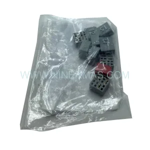
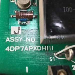
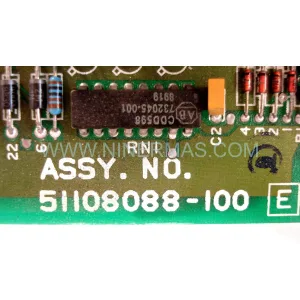
Original Industrial Spare Part
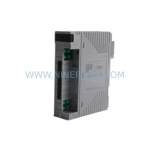
Yokogawa NR-VLCPU11EO-040708 Service-Ready Spare Part
Verify the part, confirm the platform family, and move straight into quotation with the right commercial details.
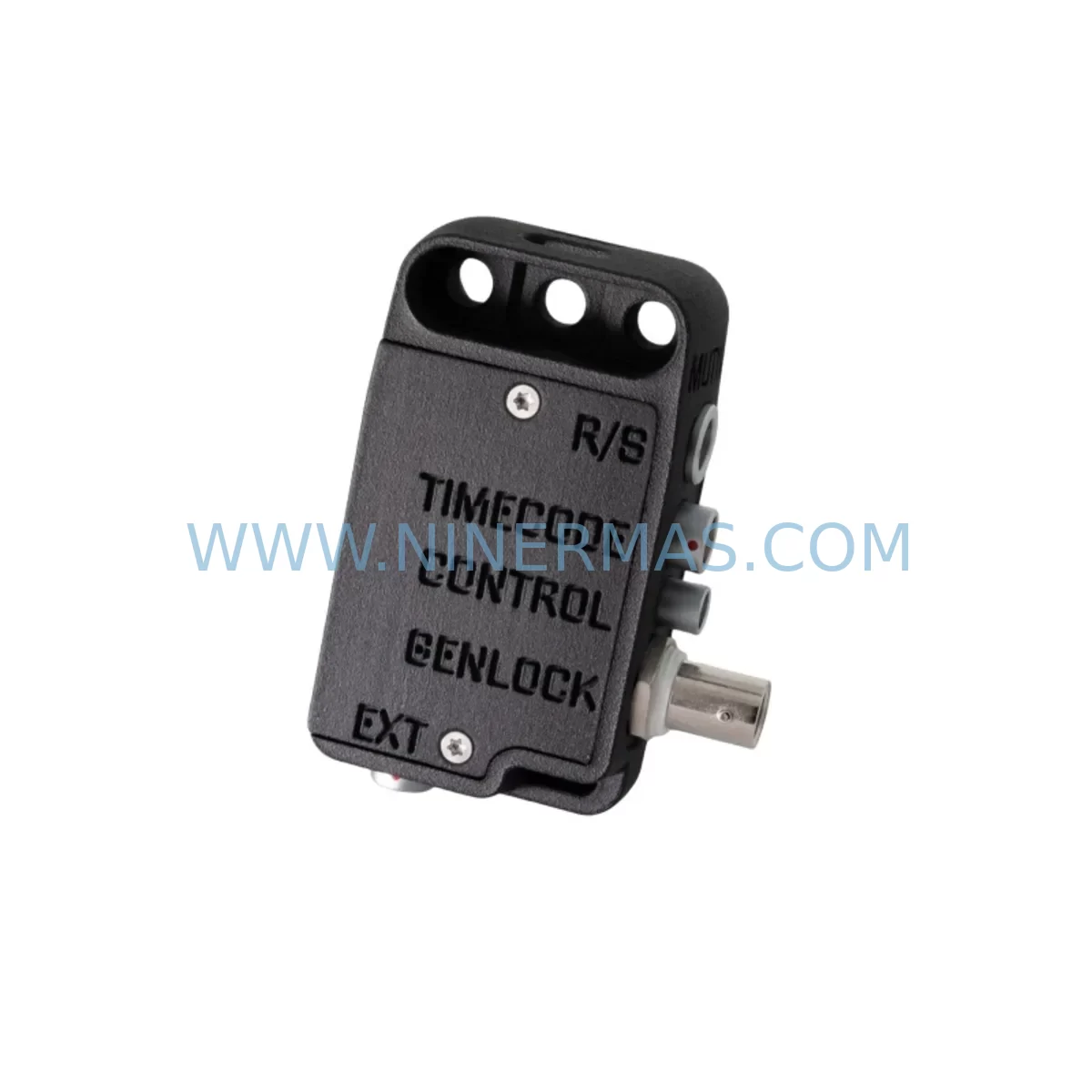
RFQ Ready
- SKUNR:VLCPU11E(O)-040708/NR:VLCPU11E(B)-040708
- CategorySIS Safety & Redundancy Systems
- BrandYokogawa
- SupportAvailability, lead time, condition, and shipping coordination
How Buyers Usually Use This Page
- Confirm the exact part number and platform family before sending the quote request.
- Use direct email when quantity, condition, and destination are already defined internally.
- Switch to the broader brand or category archive when you need alternates nearby.
Series Navigation
Move through the most common platform families behind this part.
Product RFQ
Send this part directly for quotation.
Include quantity, required condition, destination country, and target delivery timing. Current reference: Yokogawa NR-VLCPU11EO-040708 Service-Ready Spare Part with SKU NR:VLCPU11E(O)-040708/NR:VLCPU11E(B)-040708.
Yokogawa NR-VLCPU11EO-040708 Service-Ready Spare Part: Spare Replacement and Downtime Risk Control for Safety Instrumented Systems
The Yokogawa NR-VLCPU11EO-040708 and NR-VLCPU11EB-040708 are original safety CPU modules designed for the Yokogawa ProSafe-RS Safety Instrumented System (SIS). These modules serve as the central processing unit within the ProSafe-RS controller node, executing safety logic, managing I/O communication, and maintaining the functional safety integrity required in IEC 61511-compliant installations across oil and gas, petrochemical, power generation, and chemical processing facilities.
Maintaining a service-ready spare for the NR-VLCPU11EO-040708 is a fundamental requirement for any maintenance engineering team responsible for safety-critical automation infrastructure. CPU module failures in a ProSafe-RS system can trigger a full safety shutdown, halting production and initiating emergency response procedures. With a verified replacement unit on-site, maintenance engineers can restore system operation within hours rather than days, dramatically reducing mean time to repair (MTTR) and protecting both personnel safety and production continuity.
Each NR-VLCPU11EO-040708 unit supplied by NINERMAS is sourced as an original Yokogawa component, subjected to pre-shipment functional testing, and covered by a 12-month warranty. This ensures that the spare part entering your inventory is operationally verified and ready for immediate deployment when a fault event occurs.
Spare Maintenance Table
| Parameter | Specification / Detail |
|---|---|
| Primary SKU | NR-VLCPU11EO-040708 |
| Alternate SKU | NR-VLCPU11EB-040708 |
| Series | VLCPU11E / ProSafe-RS |
| Manufacturer | Yokogawa Electric Corporation |
| Country of Origin | Japan |
| Module Function | Safety CPU — executes safety logic, manages I/O bus, handles SIS communication |
| System Compatibility | Yokogawa ProSafe-RS Safety Instrumented System (SIS) |
| Safety Standard | IEC 61508 / IEC 61511 compliant; SIL 2 / SIL 3 capable |
| Operating Voltage | 24 VDC (supplied via ProSafe-RS backplane power bus) |
| Operating Temperature | 0°C to 60°C (32°F to 140°F) |
| Humidity | 10% to 90% RH, non-condensing |
| Installation | DIN-rail mounted within ProSafe-RS controller node chassis |
| Communication Interface | Vnet/IP safety network; node-level I/O bus |
| Redundancy Support | Dual-redundant CPU configuration supported |
| Maintenance Recommendation | Inspect every 12 months; replace on fault indication or SIL proof-test failure |
| Warranty | 12 months from date of shipment (NINERMAS) |
| Pre-Shipment Testing | Functional verification performed before dispatch |
| Lead Time | Subject to stock availability; reserved inventory programs available |
Maintenance Planning for Continuous Operation
When planning a replacement or inspection of the NR-VLCPU11EO-040708, maintenance engineers should treat the CPU module as part of a broader system health review. A ProSafe-RS controller node integrates multiple interdependent components, and a CPU fault event is often an opportunity to assess the condition of adjacent hardware before returning the system to service.
Begin by verifying the integrity of the ProSafe-RS backplane (NR-VLBP series), which provides the mechanical and electrical interface between the CPU and all I/O modules. Backplane connector wear or contamination can cause intermittent communication faults that are misdiagnosed as CPU failures. Inspect the backplane bus connectors and confirm seating torque on all module retaining screws.
The ProSafe-RS power supply module (such as the NR-VLPS series) should be checked for output voltage stability and ripple. An aging or undersized power supply is a common root cause of CPU resets and watchdog faults. If the power supply is approaching its recommended service interval, replace it concurrently with the CPU to avoid a repeat shutdown event.
Review the status of all safety I/O modules installed in the same node. Analog input modules (such as the AAI143-H00 series) and digital output modules (such as the ADV151-P00 series) should be inspected for channel fault indicators and calibration status. A CPU replacement is an appropriate time to perform a full I/O loop check and verify that all field signals are within expected ranges.
Inspect the node interface unit (NIU) and associated Vnet/IP communication modules (CP451-10 or equivalent) for firmware version alignment with the replacement CPU. Mismatched firmware between the CPU and communication modules can prevent the node from rejoining the safety network after restart. Confirm that the replacement NR-VLCPU11EO-040708 carries the correct firmware revision for your installed ProSafe-RS system version.
Check all terminal boards and field wiring terminations connected to the I/O modules in the affected node. Loose terminals, corroded connections, or damaged cable shields are frequently discovered during unplanned maintenance events and should be corrected before the system is returned to automatic mode. Pay particular attention to signal isolators and safety barriers installed between field instruments and the I/O modules, as these components protect the SIS from field-side overvoltage and ground faults.
If the ProSafe-RS node communicates with a Yokogawa CENTUM VP DCS via the Vnet/IP network, verify that the DCS engineering station reflects the correct node status after CPU replacement. Update the system configuration database if the replacement CPU carries a different hardware revision code. Confirm that any HMI faceplates associated with the safety functions controlled by this node display correct status before releasing the system to operations.
For facilities operating dual-redundant CPU configurations, the replacement of one CPU module should be followed by a synchronization check to confirm that the standby CPU has successfully loaded the current safety application and is in hot-standby mode. Do not return the system to normal operation until both CPUs report synchronized status.
Procurement engineers should consider establishing a reserved inventory program for the NR-VLCPU11EO-040708 and NR-VLCPU11EB-040708. Given that Yokogawa ProSafe-RS systems are deployed in long-lifecycle safety applications, the risk of obsolescence and extended lead times increases as the installed base ages. Securing a minimum of one spare CPU module per ProSafe-RS node — with a secondary unit held at a regional warehouse — provides a two-tier buffer against unplanned downtime caused by supply chain delays.
Site Replacement Workflow
The following workflow is recommended for on-site replacement of the NR-VLCPU11EO-040708 in a ProSafe-RS safety system:
Step 1 — Pre-Replacement Authorization: Obtain a Management of Change (MOC) approval and a Permit to Work (PTW) before initiating any work on the safety system. Notify the control room and operations team of the planned maintenance window. Confirm that the process is in a safe state or that appropriate bypass procedures are in place per your site’s Safety Management System.
Step 2 — Backup and Documentation: Using the ProSafe-RS Engineering Environment (SENG), export the current safety application project and configuration to a secure backup location. Record the firmware version, hardware revision, and node address of the existing CPU module. Photograph the module label and connector positions before removal.
Step 3 — Module Removal: Power down the affected node following the ProSafe-RS hardware maintenance procedure. Release the CPU module retaining latch, disconnect any external cables, and remove the module from the backplane slot. Handle the module using ESD-safe procedures and place it in an anti-static bag for return or failure analysis.
Step 4 — Replacement Installation: Insert the NR-VLCPU11EO-040708 replacement module into the correct backplane slot. Confirm that the module is fully seated and the retaining latch is engaged. Reconnect any external cables in the correct orientation. Power up the node and observe the CPU status LEDs for normal startup indication.
Step 5 — Configuration Restore and Verification: Using the ProSafe-RS Engineering Environment, download the safety application to the replacement CPU. Verify that the application checksum matches the backup. Perform a full I/O loop check and confirm that all safety functions are operating correctly. For redundant configurations, confirm hot-standby synchronization before releasing the system.
Step 6 — Return to Service: Remove any bypasses applied during the maintenance window. Notify operations that the safety system is restored to normal automatic mode. Update the maintenance management system (CMMS) with the replacement record, including the new module serial number and date of installation.
Spare Parts Support FAQ
Q1: Is the NR-VLCPU11EO-040708 supplied by NINERMAS an original Yokogawa component?
Yes. All NR-VLCPU11EO-040708 and NR-VLCPU11EB-040708 units supplied by NINERMAS are original Yokogawa Electric Corporation components. Each unit undergoes pre-shipment functional testing to verify operational integrity before dispatch. A 12-month warranty is provided from the date of shipment.
Q2: How do I confirm compatibility between the replacement CPU and my installed ProSafe-RS system version?
Compatibility is determined by the ProSafe-RS system version, firmware revision, and hardware generation of your installed node. Before ordering, provide NINERMAS with your current system version and the hardware revision code from the existing CPU module label. Our technical team will confirm compatibility and advise on any firmware alignment requirements prior to shipment.
Q3: What is the recommended spare parts inventory strategy for ProSafe-RS CPU modules?
For facilities with multiple ProSafe-RS nodes, we recommend maintaining a minimum of one NR-VLCPU11EO-040708 spare per node type, with a secondary unit held at a regional distribution point. For critical single-node installations, a hot-spare held on-site is advisable. NINERMAS offers reserved inventory programs that guarantee stock availability and fixed pricing over a defined contract period, reducing procurement risk for long-lifecycle safety systems.
Q4: What is the lead time for the NR-VLCPU11EO-040708, and can NINERMAS support emergency orders?
Lead time varies based on current stock levels. In-stock units can be dispatched within 24–48 hours of order confirmation. For emergency requirements, contact NINERMAS directly to confirm availability and arrange expedited shipping. We maintain long-term supply commitments for ProSafe-RS components to support customers with ongoing maintenance programs and annual inspection schedules.
| Product Series | ProSafe-RS |
|---|---|
| Country of Origin | JP |
Catalog Continuation
More Yokogawa modules in the catalog.
Use the brand lane to compare nearby part numbers, platform-adjacent modules, and other inquiry-ready listings before sending your final RFQ.
Catalog Continuation
Alternative parts within SIS Safety & Redundancy Systems.
Stay inside the same system family when you need substitutes, adjacent modules, or a broader shortlist for procurement review.